OEM/ODM Aluminum Die/Iron Foundry Casting for Industrial Machinery | CNC Machining
Let’s define your requirement
Send a product link, drawing or short brief. We’ll work through the details with you.
- Confirm the specificationGrade or model, size and intended use.
- Define your orderQuantity, finish or configuration, and samples.
- Agree the quotation scopeIncluded work, key checks and delivery needs.
-
Surface FinishPainted , Anodized
-
MaterialAluminum Alloy
-
Surface treatmentPainting Anodizing ElectroplatingApplicationIndustry Machinery
-
ProcessCasting +Machining(if Need)+surface TreatmentToleranceCustomer's Drawing Request
-
MOQ100 PiecesQuality ControlProfessional Inspection
-
Lead Time20-35 DaysDrawing format2D/(PDF/CAD)3D(IGES/STEP)
-
ServiceOEM ODM Customised
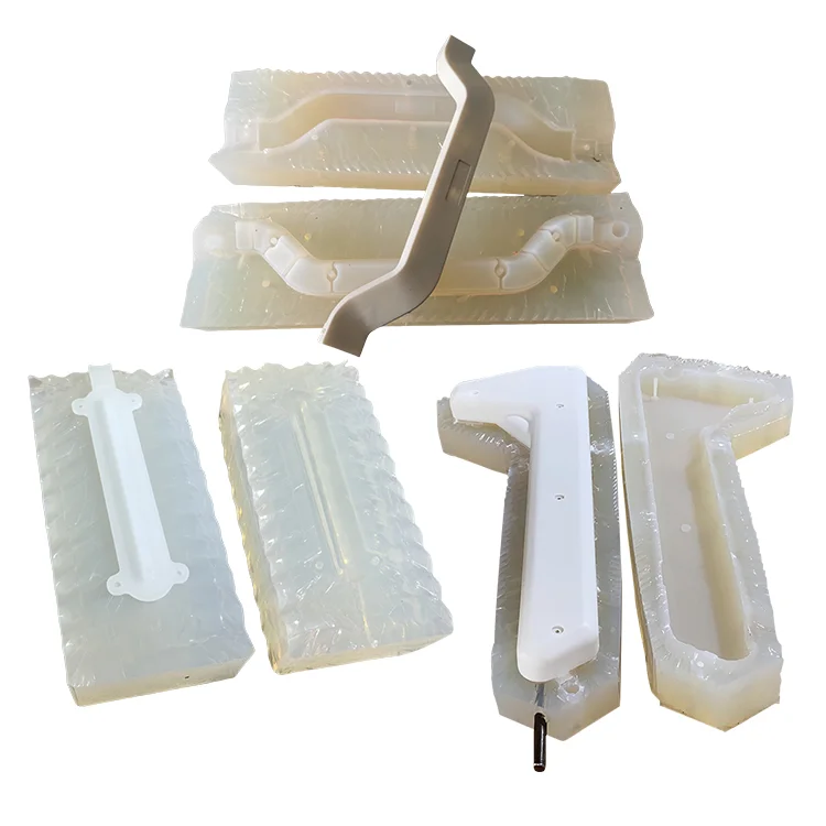
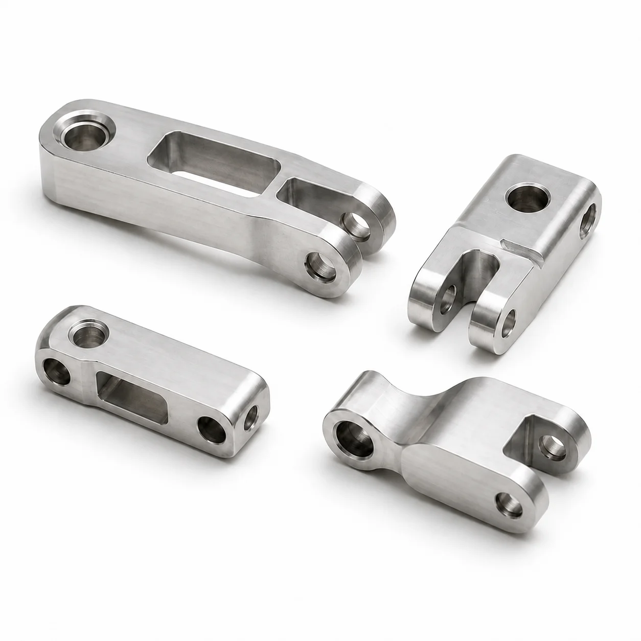
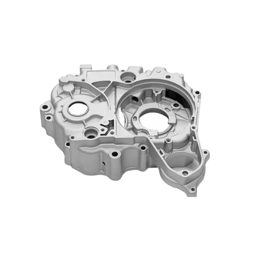
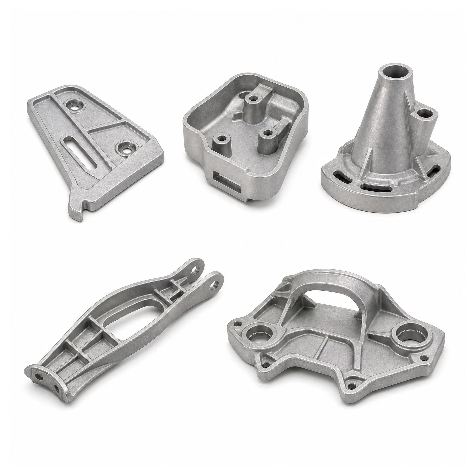
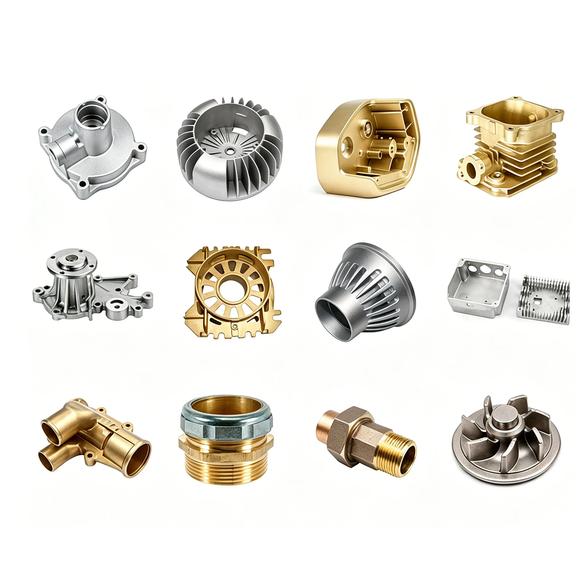
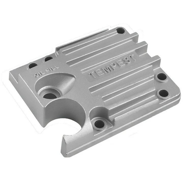
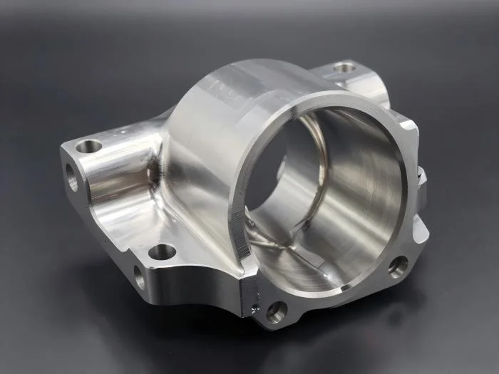
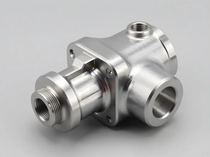
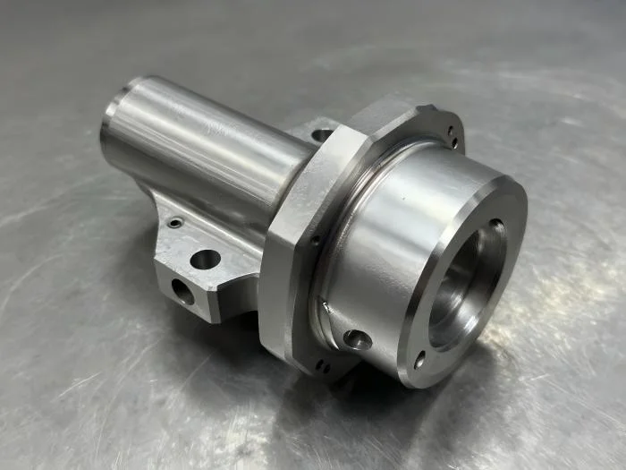
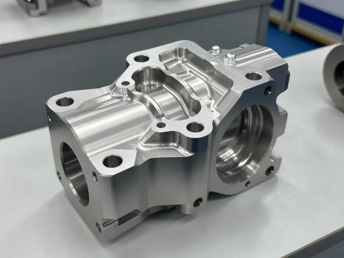
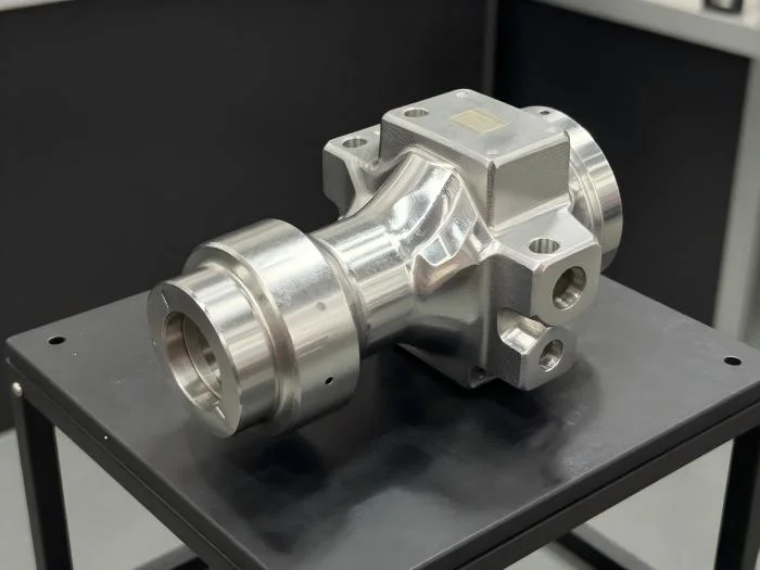
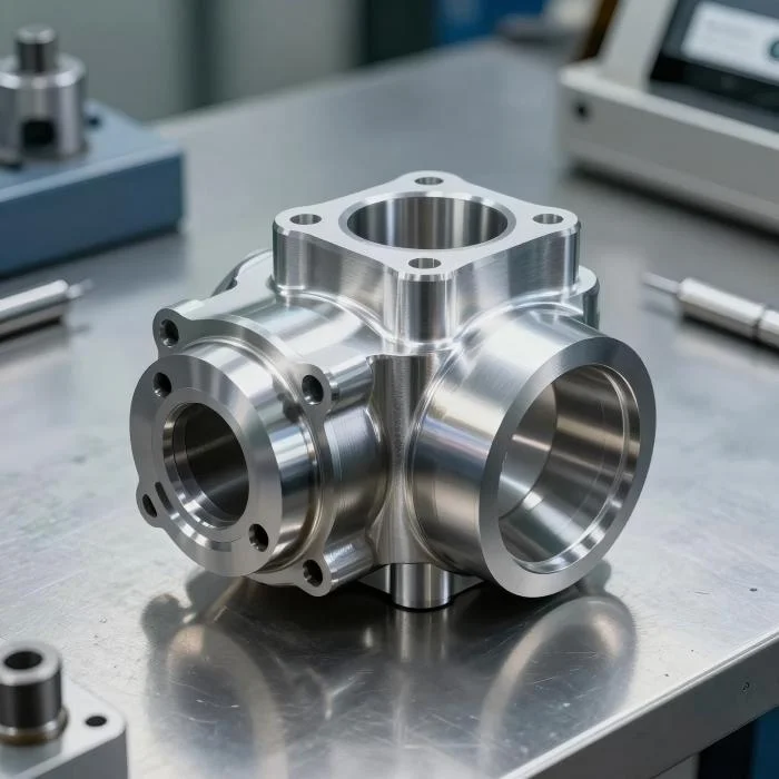
OEM/ODM industrial machinery components include aluminum die-casting and iron foundry directions, with CNC machining available for the custom work. Aluminum-alloy production can combine casting, machining when needed and surface treatment. The actual component defines which material and manufacturing scope are required for its industrial use.
Define the foundry and CNC work
Choose the aluminum or iron direction for the requested part and establish its actual grade. Identify the geometry to be produced through casting and any areas requiring subsequent machining. For the aluminum-alloy route, decide where machining is needed before agreeing the finished condition, so that the casting and CNC requirements describe the same component.
Choose painting, anodizing or electroplating
Painting, anodizing and electroplating are the available surface-treatment directions. Select the treatment applicable to the chosen material and identify the areas to be treated. Relate the surface requirement to the component drawing and intended machinery use, including the condition expected when dimensions and treated surfaces are inspected. Keep the selected finish explicit in the inspection criteria.
Connect drawing tolerances with inspection
Tolerances follow the customer's drawing request, and professional inspection supports the custom component scope. Inputs include 2D PDF/CAD and 3D IGES/STEP. Use those inputs to identify the controlling dimensions, the required casting and machining operations, and the selected finish. Agree the dimensional and surface acceptance for the industrial machinery part before finalizing its OEM/ODM manufacturing requirements.