
CUSTOM MANUFACTURING · PROJECT REVIEW
Custom Exhaust Flanges for Construction Vehicles
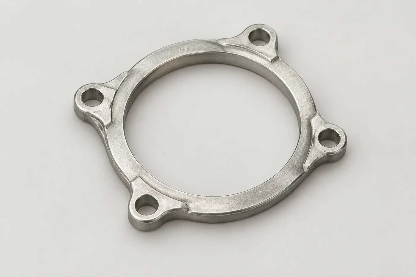
Relia reviews exhaust flanges around the gasket face, bolt pattern and pipe opening. Use the actual connection drawing, selected material and service context to define the casting, machining and interface checks for your vehicle project.
RELIA · PRODUCT AND MANUFACTURING SUPPORT
Define the flange and connection scope
Relia's exhaust-flange reference lists stainless, alloy steel, cast iron and carbon steel options with customized machining. Relia connects the selected grade and surface condition to your gasket and mating pipe or manifold. The enquiry can then distinguish a standalone flange from a joined pipe/flange package and define the checks appropriate to each.
| Your requirement | Relia product and service scope |
|---|---|
| Use | Engineering/construction-vehicle exhaust connection |
| Materials | Specified stainless, alloy steel, cast iron or carbon steel |
| Files | 2D JPG/PDF and 3D STEP/STP |
| Functional features | Gasket face, bolt pattern, port and joint thickness |
02 · INTERFACES
Match the bolt pattern to the pipe geometry
- Connection geometry
- Keep holes, centres and flow opening on one drawing.
- Mating compatibility
- Compare the flange with the actual pipe arrangement.
Keep hole locations, centre relationships and the flow opening on one controlled drawing. A similar-looking ring is a form reference rather than proof of compatibility with an existing vehicle.
Technical notes
Define the sealing face and the datum used for hole position. A catalogue 0.01 mm field should not be applied indiscriminately to the casting or entire flange. Specify material-specific finishing rather than assuming passivation is appropriate for every steel or iron option.
MANUFACTURING ROUTE · FEATURES AND CONTROL
Finish the Seal and Fastener Geometry After Forming
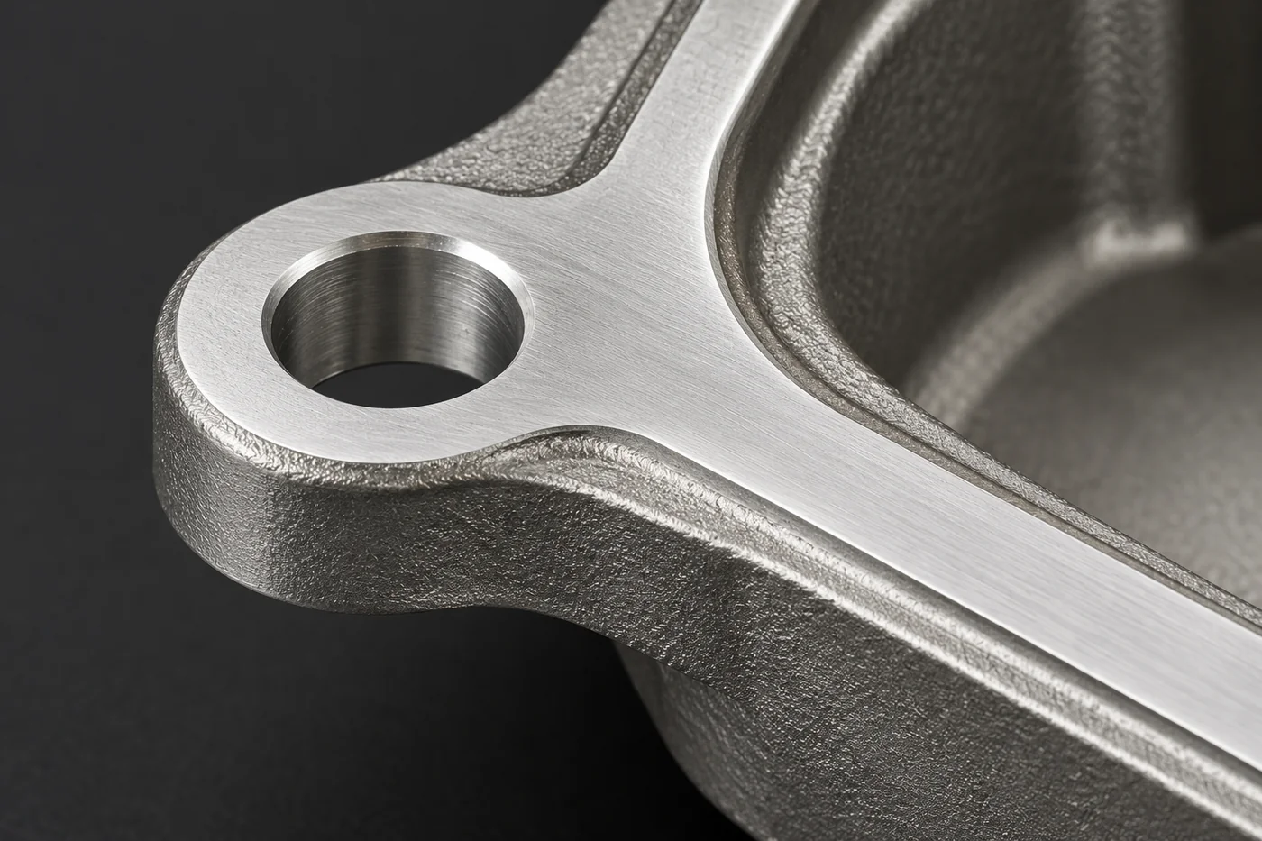
The chosen blank route retains material on the sealing face and around the finished port and holes. Relia's machining review uses the nominated datums to control flatness, thickness and the port-to-bolt relationship. Surface treatment is selected for the actual alloy rather than applied as a universal finish. When the flange is joined to another part, the process plan also needs to identify whether final face work or an assembly leakage check follows joining, because the delivered joint must retain the required geometry.
- Define the mating jointGasket, port, bolt pattern and temperature duty
- Prepare the blankSpecified alloy and machining allowance
- Machine and finishSeal face, holes and material-specific treatment
- Approve the connectionDimensions, fit and any included assembly check
04 · MACHINING
Plan the sealing interface as a finished feature
- Sealing feature
- Define the gasket face and required surface state.
- Machining datums
- Relate that face to the opening and mounting holes.
Identify the sealing face, opening and locating datums that need controlled machining. Include the surface and dimensional requirements used by the mating arrangement.
05 · ACCEPTANCE
Agree dimensional and assembly checks
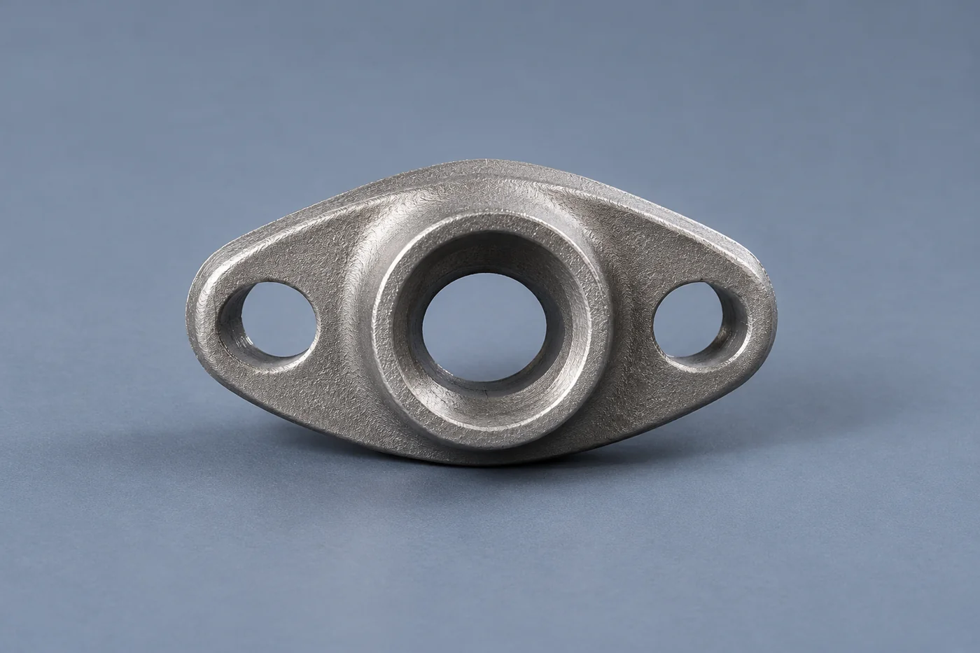
Check flatness, thickness, bolt position and port alignment after the specified operations. Where the flange is supplied with a pipe or manifold, state whether joining and assembly leakage checks are included. Final engine or vehicle approval remains separate from flange manufacture.
06 · DELIVERY
Protect finished flanges during handling
- Surface protection
- Identify sealing areas and threads needing protection.
- Variant identity
- Retain part numbers and revisions for similar flanges.
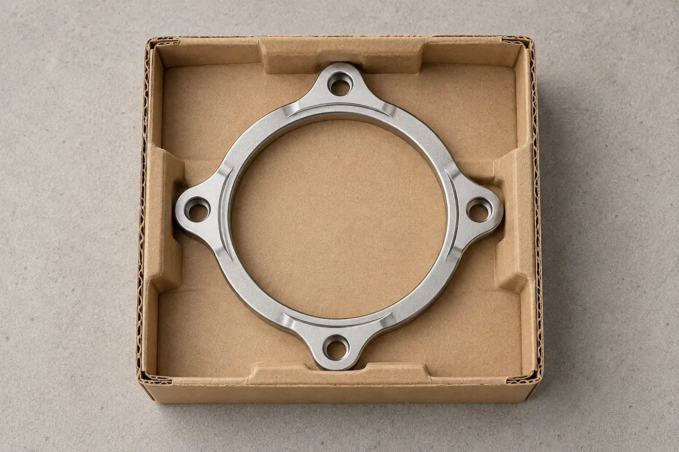
Identify the sealing surfaces and threads requiring protection. Keep the part number and revision clear where similar flange variants are supplied together.
07 · QUOTATION
Retain one connection definition for the order
The material, bolt pattern, machining and required records should describe the same flange. Make missing mating inputs visible before the manufacturing package is agreed.
Technical notes
Identify the mating flange, gasket type, bolt pattern, port opening and available fastener access. Include service temperature and the restraint imposed by nearby pipework. A replacement must preserve the installed relationship, not just the outer flange profile.
| Record | Retain |
|---|---|
| Geometry | Current connection drawing |
| Manufacture | Material and finished condition |
| Acceptance | Required checks and fit review |
CONNECTED BUYING GUIDES
Continue with the next project decision
Follow the related component and purchasing guides, or open the catalogue reference to carry this requirement into a specific project enquiry.
RELIA · YOUR NEXT PROJECT
Share the flange and mating-pipe requirements
Send the drawing, bolt pattern, material and quantities. Include the exhaust-duty context and required interface checks. We can review the manufacturing scope against the actual connection definition.
Start with these project details
- Flange drawing and bolt pattern
- Material and quantities
- Exhaust-duty conditions
- Sealing and interface checks
Shuyuan Road, Qingdao, Shandong, China
