
CUSTOM MANUFACTURING · PROJECT REVIEW
Custom Aluminum Heat Sinks for Power Equipment
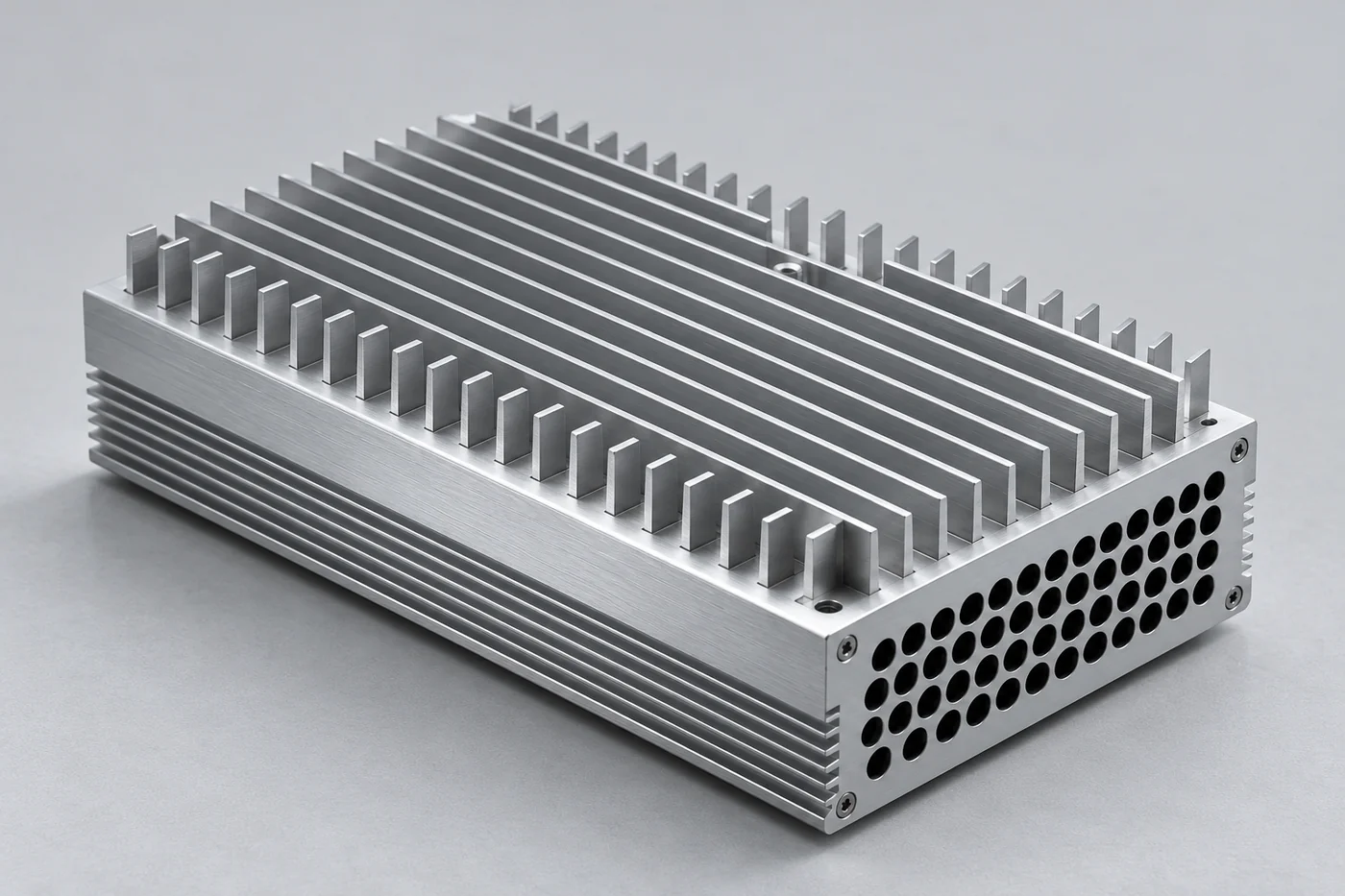
A useful heat-sink enquiry connects the component to its thermal and mounting conditions. Relia reviews the alloy, fin geometry and manufacturing route, while the equipment's heat load, airflow and validation basis define the performance requirement.
RELIA · PRODUCT AND MANUFACTURING SUPPORT
Bring the thermal and installation constraints together
Relia's heat-sink reference identifies 6063 aluminium and a 1,000-piece minimum for that item. Relia's enquiry links the section geometry to machining, mounting and the required surface finish. The production route is reviewed for the actual fin design; a 6063 material reference alone does not establish that a particular heat sink is pressure die cast.
| Your requirement | Relia product and service scope |
|---|---|
| Material reference | 6063 aluminium |
| Listed minimum | 1,000 pieces on this heat-sink item |
| Design inputs | Heat load, ambient, airflow and allowable temperature |
| Critical surface | Device contact base and mounting interface |
02 · MANUFACTURING ROUTE
Review the fin form against the proposed process
- Fin geometry
- Show spacing, height, base and mounting features.
- Manufacturing route
- Confirm the exact alloy and proposed forming process.
Fin spacing, height, base geometry and connection features affect the forming discussion. Confirm the exact alloy and route before the component is quoted as a casting or another manufacturing form. We review the actual drawing and its features rather than treating an aluminum grade name as proof of a particular process.
Technical notes
Use fin height, spacing and orientation to match the installation rather than copying a larger fin count. The base flatness, contact pressure and thermal-interface thickness affect the device-to-sink path. Separate these requirements from cosmetic anodizing or colour selection.
MANUFACTURING ROUTE · FEATURES AND CONTROL
Form the Fins and Finish the Thermal Contact Path
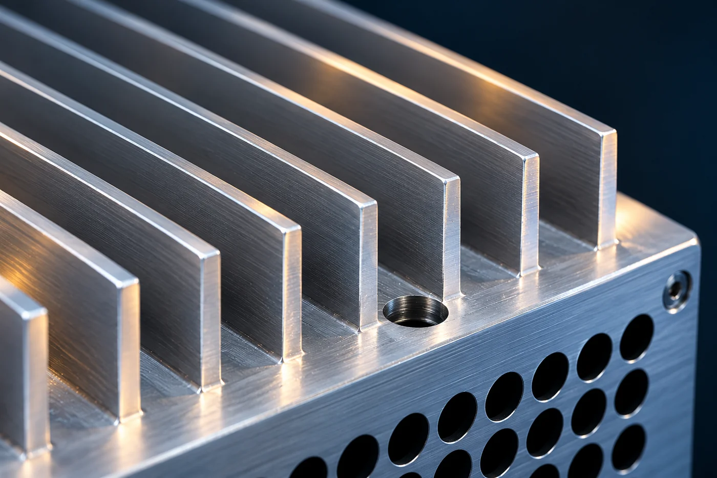
A continuous fin section can lead to an extrusion-and-cutting proposal, while other geometries may require machining or a separately reviewed casting route. Relia's manufacturing review begins with that shape rather than assuming one process for every heat sink. The base and mounting holes are then finished for the device interface, with deburring that leaves airflow passages clear. Flatness, surface condition, interface-material thickness and clamp pressure all affect the contact path, so thermal approval uses the intended assembled configuration.
- Review the fin geometrySection shape, material and practical route
- Create the blankSelected forming/cutting or machining process
- Finish the contact baseMounting pattern, flatness and deburred passages
- Validate in service conditionsHeat load, interface material and airflow
04 · FINISHING
Keep surface treatment separate from the contact requirement
- Surface finish
- Identify treatment and visible appearance requirements.
- Thermal contact
- Mark contact areas needing separate finish or masking.
Identify the treatment and visible finish you need, together with any contact areas that require different handling or masking. The effect of a finish belongs in the thermal design and validation review. We agree the supplied surface condition without applying an unsupported performance-improvement percentage.
05 · EVIDENCE
Distinguish component inspection from thermal validation
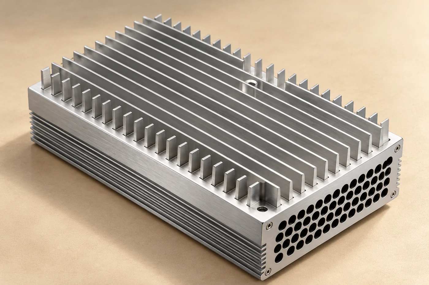
Approve contact dimensions and mounting fit, then assess thermal performance in the intended airflow and assembled condition. The catalogue's general 0.01 field lacks sufficient feature context for an overall tolerance claim. Define flatness, contact finish and test conditions explicitly.
| Evidence level | Decision it supports |
|---|---|
| Component inspection | Material and geometry match the requirement |
| Assembly review | Contact and mounting arrangement are accepted |
| Thermal validation | The defined system meets its project target |
| Change review | Affected evidence remains applicable |
06 · PROTOTYPE REVIEW
Use samples with the intended assembly conditions
- Assembly conditions
- Review the sample with its intended contact and mounting.
- Retained validation
- Record changes affecting the accepted test configuration.
Review the sample with the contact arrangement and mounting conditions used by the equipment design. If its material, geometry or manufacturing route changes later, identify the affected validation. Keep the accepted component and relevant test configuration recorded so the next order follows the same technical basis.
07 · QUOTATION BOUNDARY
Keep design support and manufacturing scope clear
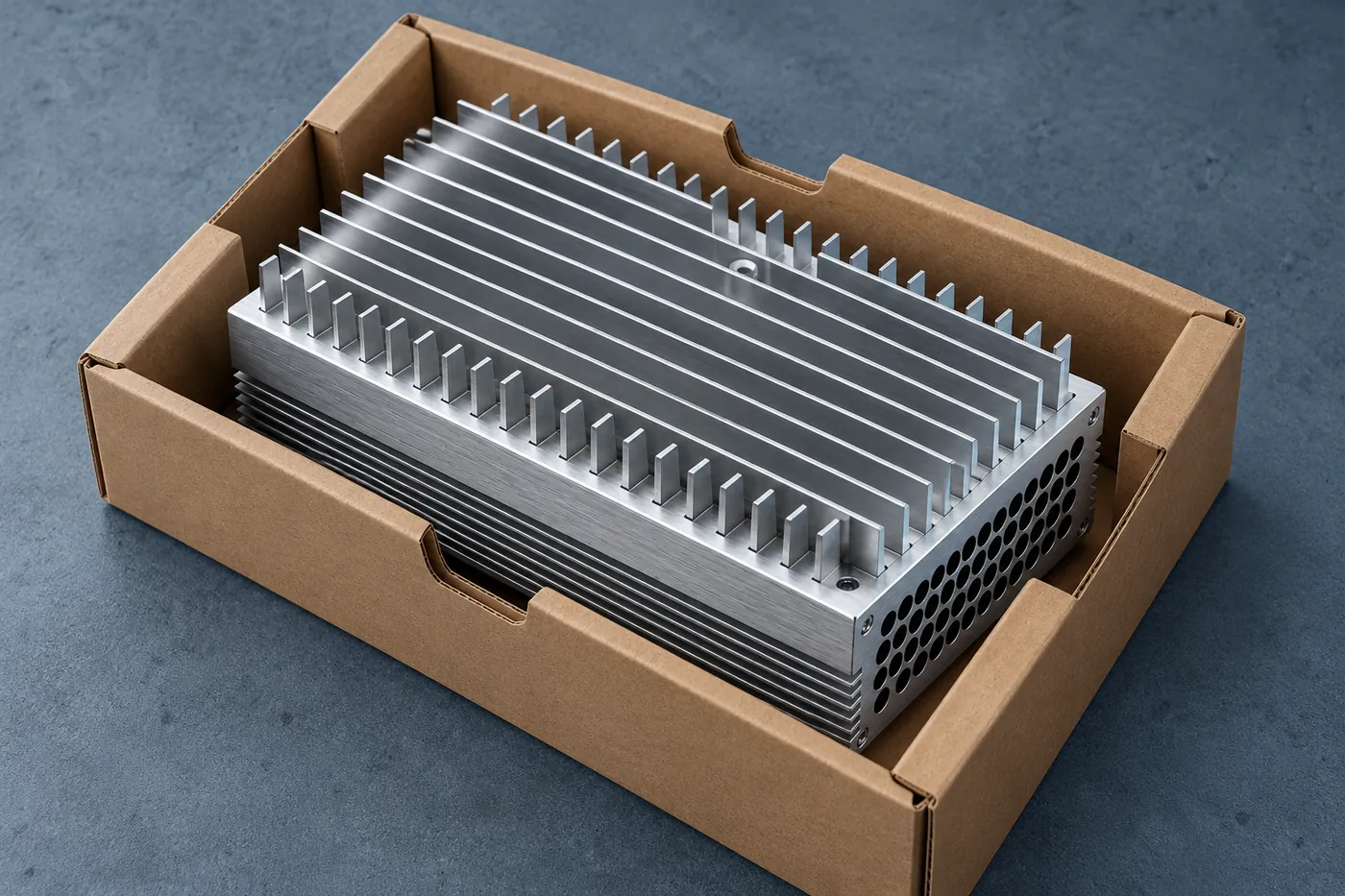
Tell us whether the enquiry is for manufacturing a defined part or includes a separate design-review request. Keep the supplied geometry, finish and verification work visible in the quotation. That helps both teams identify the information needed before the component can move to its next approval stage.
Technical notes
Provide heat dissipation, ambient temperature, available airflow and the permitted device temperature. Include the mounting pattern and interface material. A heat sink that fits the enclosure can still perform differently when airflow is blocked or the contact interface adds thermal resistance.
CONNECTED BUYING GUIDES
Continue with the next project decision
Follow the related component and purchasing guides, or open the catalogue reference to carry this requirement into a specific project enquiry.
RELIA · YOUR NEXT PROJECT
Send the fin model and thermal-design constraints
Share the component model, contact and mounting requirements, selected alloy and quantities. Include the thermal targets and validation scope already defined for the equipment. We can review the manufacturing route and delivered-component package with those constraints visible.
Start with these project details
- Model and contact interface
- Alloy, route and quantities
- Heat load and airflow context
- Thermal targets and validation scope
Shuyuan Road, Qingdao, Shandong, China
