
CUSTOM MANUFACTURING · PROJECT REVIEW
Custom Stainless Actuator Brackets for Valve Automation Retrofits
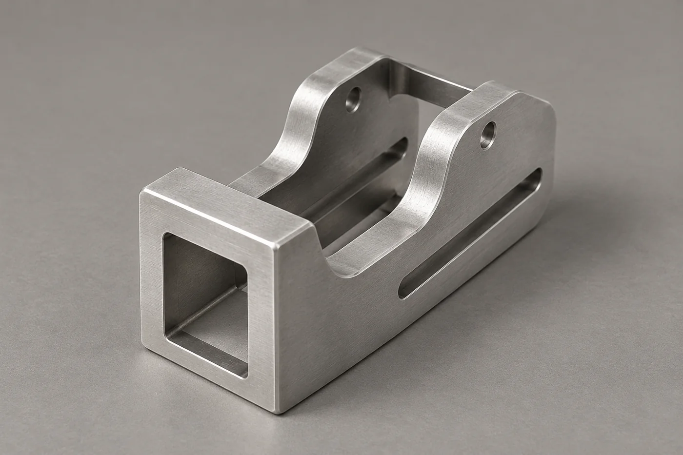
A valve-actuator bracket must align two interfaces and leave room for assembly. Relia reviews custom stainless casting and machining around the valve, actuator and coupling arrangement, so the delivered bracket follows the actual retrofit drawing.
RELIA · PRODUCT AND MANUFACTURING SUPPORT
Record both sides of the mounting relationship
Relia's actuator-bracket reference covers 304/316 stainless options with casting, machining and specified finish. Relia's drawing-based service can address a custom hole pattern and the space between the valve and actuator. The bracket is reviewed together with coupling dimensions and fastener access, so the manufacturing scope follows the actual retrofit rather than a single bolt circle.
| Your requirement | Relia product and service scope |
|---|---|
| Materials | 304/316 stainless options |
| Route | Casting, optional machining and specified finish |
| Retrofit inputs | Valve interface, actuator interface, coupling and clearance |
| Critical relationship | Drive axis and mounting-face alignment |
02 · INSTALLATION GEOMETRY
Keep alignment and access visible
- Operating centreline
- Show alignment between valve and actuator.
- Installation space
- Include coupling access and nearby obstructions.
Show the centreline relationship, available envelope and the access needed for assembly or operation. Include nearby parts that could interfere with the bracket. The review can then consider mounting geometry and practical installation space together, with the important features retained on the controlled drawing.
Technical notes
Keep cast shape and machined alignment separate. The catalogue's 0.02 mm tolerance field should be assigned only to agreed features; it is not an automatic limit for the whole casting. Review wall sections, tool access and mounting-face datums with the torque and support loads supplied by your design team.
MANUFACTURING ROUTE · FEATURES AND CONTROL
Cast the Support and Machine the Alignment Features
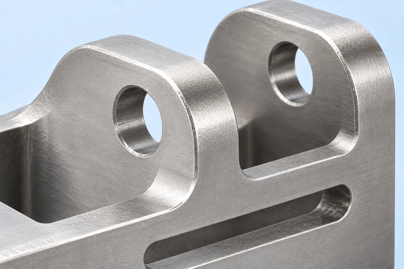
Investment casting can form the support body, gussets and transitions without building the bracket from separate welded plates. The pattern and casting design retain stock where mounting planes or holes need machining. Relia's finished-feature review relates both mounting faces and the drive-axis position to a consistent datum system. Drilling, reaming or other specified machining establishes the interfaces, while surface finishing preserves their contact condition. A representative assembly check then shows whether the coupling and fasteners remain usable.
- Map both interfacesValve pattern, actuator pattern and coupling envelope
- Form the supportCast walls, transitions and machining allowance
- Machine common datumsFaces, locating holes and alignment relationship
- Trial the retrofitCoupling fit, fastener access and moving clearance
04 · MACHINING
Plan the finished mounting faces and holes
- Machined interfaces
- Identify mounting faces, holes and locating datums.
- Finished relationship
- Include treatment effects in the dimensional requirement.
Identify the holes, faces and datums that need machining after casting. Include any surface treatment that could affect their finished relationship. We review the dimensional and inspection scope around those actual interfaces so the bracket is defined as a finished mounting component.
05 · APPROVAL
Agree the checks needed for the retrofit
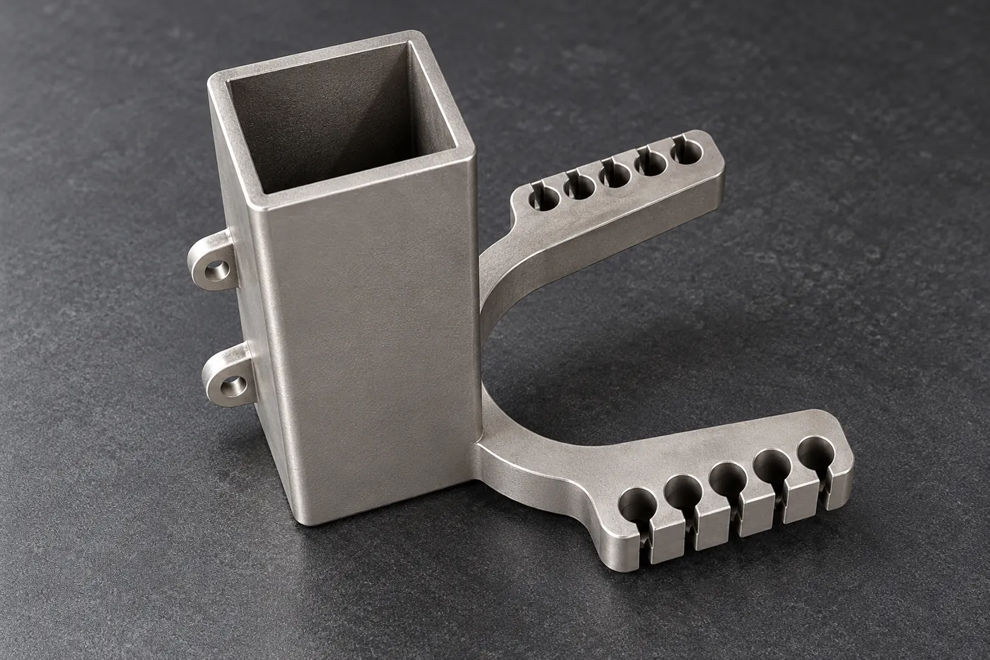
Check face parallelism, hole position and axis relationship using the agreed datums. Trial-fit with the nominated coupling and hardware where required. The bracket enquiry does not itself establish actuator sizing or a safe operating torque for the complete valve assembly.
06 · REPEAT ORDERS
Keep the bracket identity with the installation drawing
- Installation identity
- Link the bracket number to the accepted assembly drawing.
- Supplied package
- Clarify fasteners, coupling parts and drawing revisions.
Retain the bracket drawing number, revision and accepted installation relationship. Clarify which fasteners and coupling items belong to the supplied package. That record helps purchasing and installation teams request the same configuration again, with changes directed to the correct technical reference.
07 · QUOTATION BASIS
Release the manufacturing package after interface review
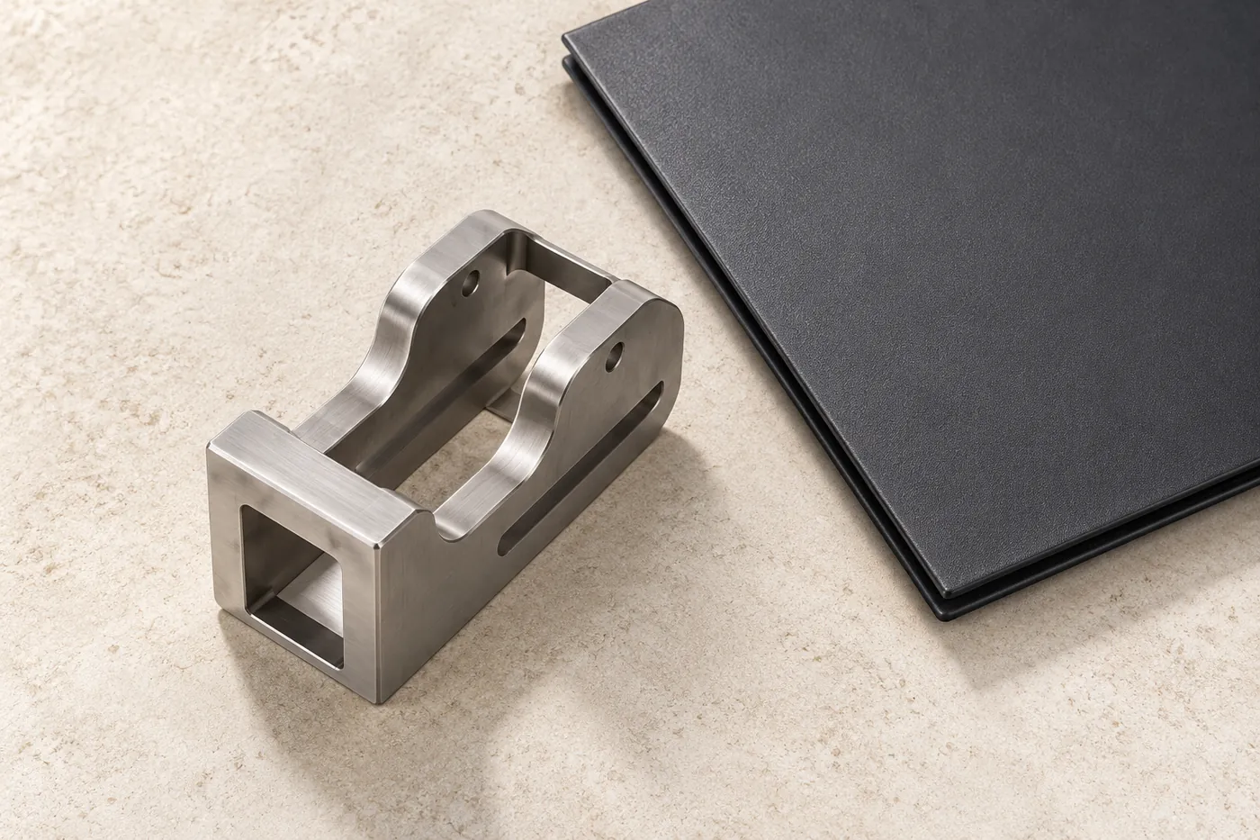
The quotation should follow the accepted mounting definition, selected material and finished condition. List the machining, finishing and required records included, with unresolved inputs kept visible. We can then review the bracket as a defined component within your wider valve-automation project.
Technical notes
Measure both interfaces: bolt pattern, mounting-face separation, shaft axis and available envelope. Include the coupling dimensions and the actuator orientation. A bracket that matches one bolt circle can still offset the drive axis or prevent removal of fasteners after installation.
| Package area | Agreement to retain |
|---|---|
| Interfaces | Both mounting sides and alignment |
| Manufacture | Casting, machining and finish |
| Verification | Dimensional and specified application checks |
| Included items | Bracket and expressly agreed accessories |
CONNECTED BUYING GUIDES
Continue with the next project decision
Follow the related component and purchasing guides, or open the catalogue reference to carry this requirement into a specific project enquiry.
RELIA · YOUR NEXT PROJECT
Send the actuator and valve mounting requirements together
Share both interface drawings, the available envelope, material requirement and quantities. Add the operating constraints and approval checks your retrofit needs. We can review the cast-bracket and finished-machining scope with the actual assembly relationship in view.
Start with these project details
- Valve and actuator interfaces
- Coupling and clearance envelope
- Stainless grade and quantities
- Installation and approval checks
Shuyuan Road, Qingdao, Shandong, China
