
CUSTOM MANUFACTURING · PROJECT REVIEW
Rigid and Flexible Overmoulded Prototype Parts
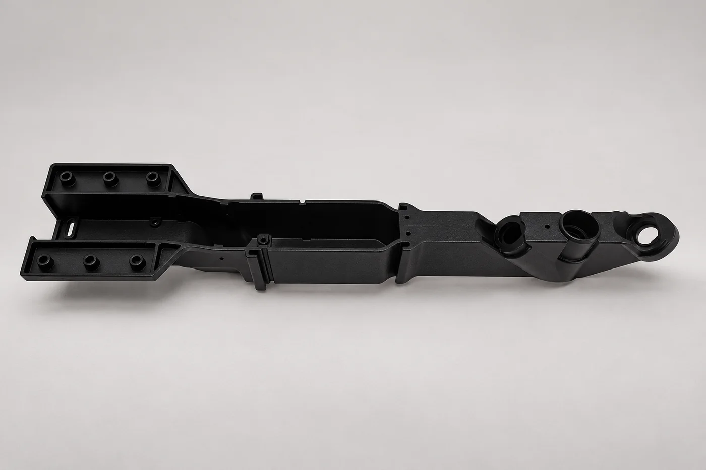
An overmoulded prototype must keep its rigid and flexible regions in the intended relationship. Relia reviews the two-material design, silicone-mould route and interface requirements, with retention, feel and appearance assessed on the actual prototype.
RELIA · PRODUCT AND MANUFACTURING SUPPORT
Define the two-material prototype
Relia's prototype reference includes vacuum casting, silicone moulding and overmoulding, with one-piece enquiries and a ±0.15 mm per 100 mm dimensional reference. Relia connects the rigid substrate, flexible region and any insert to the intended trial. Your team can then review grip, cushioning or movement with a defined material pair and interface.
| Your requirement | Relia product and service scope |
|---|---|
| Route | Vacuum casting, silicone moulding and overmoulding |
| Inputs | Separate material-region CAD and any insert drawing |
| Interface review | Adhesion, mechanical retention and datum access |
| Approval focus | Relative position, flexibility, appearance and specified retention |
02 · COMPATIBILITY
Review the material pair and interface conditions
- Material pair
- Specify each region and any insert requirement.
- Interface behaviour
- Define the bonding or retention criteria to review.
Share the exact material requirements and any relevant bonding or retention criteria. We review the proposed combination without assuming that every pair forms the same chemical bond or mechanical connection.
Technical notes
Agree the rigid and flexible grades, hardness, colour and interface design. Mechanical retention and adhesion need a deliberate review; they should not be assumed from an overmoulded appearance. Keep critical datum surfaces accessible after the second material is added.
MANUFACTURING ROUTE · FEATURES AND CONTROL
Control Both Material Regions and Their Interface
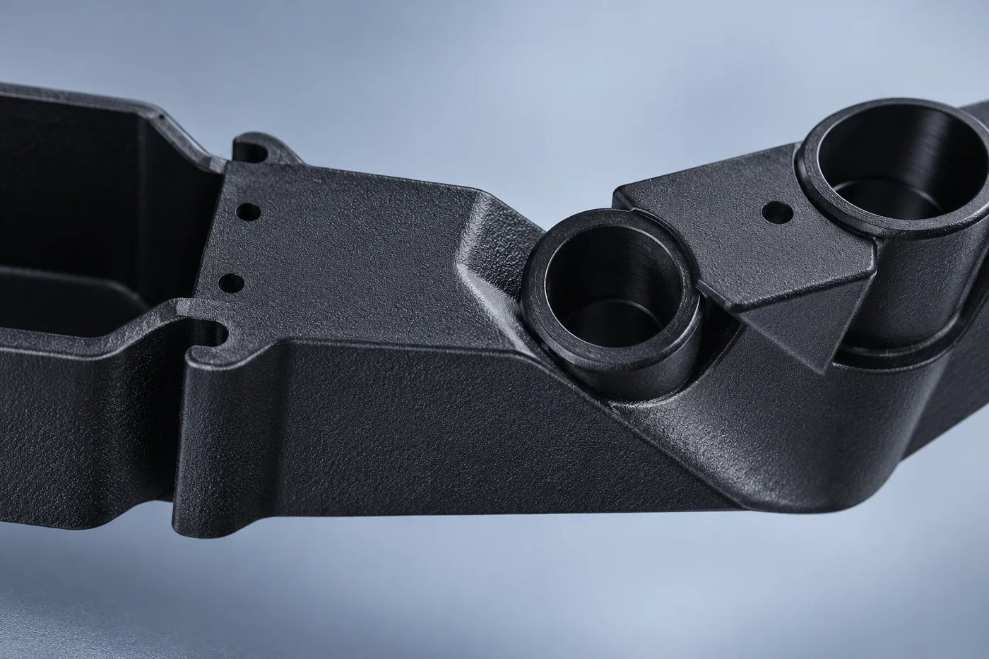
The route begins with the rigid geometry and the location of the second material. Moulding and any insert positioning need to retain that relationship while the flexible material is cast and cured under its own material instructions. Relia's review identifies the surfaces that locate the prototype and the mechanical retention or adhesion requirement at the interface. Demoulding and trimming should preserve the trial's flexible features. Fit and deformation are then evaluated together, rather than treating a successful appearance sample as a complete bond-performance result.
- Separate the CAD regionsRigid, flexible and any insert geometry
- Plan the interfaceLocation, retention and material compatibility
- Cast and finish the sampleSelected grades and material-specific cure
- Trial the combined partFit, deformation and specified retention checks
04 · FINISH
Specify colour, surface and mating requirements
- Separate surfaces
- Identify colour and finish for each material region.
- Assembly interfaces
- Keep mating requirements visible in the combined design.
Identify visible regions and the interfaces used by the assembly. Agree the required finish for each material region rather than treating the combined part as one uniform surface.
05 · APPROVAL
Validate the interface and intended function
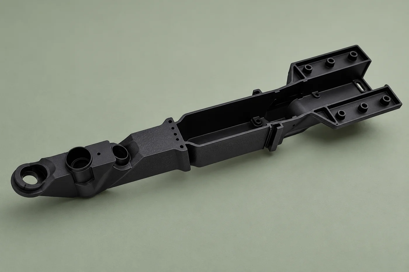
Inspect the relative position of the two regions and trial the intended deformation. Define any bond or retention check for the prototype. A successful appearance sample is not proof of long-term adhesion, chemical resistance or performance of the final production material pair.
06 · CHANGES
Keep prototype iterations identifiable
- Trial version
- Record material-pair and geometry changes together.
- Next decision
- Identify which checks are affected by another iteration.
Record material-pair and geometry changes together. Retain the trial version and identify affected checks before another iteration is accepted or passed toward a production-route review.
07 · PURCHASING
Quote the combined development work clearly
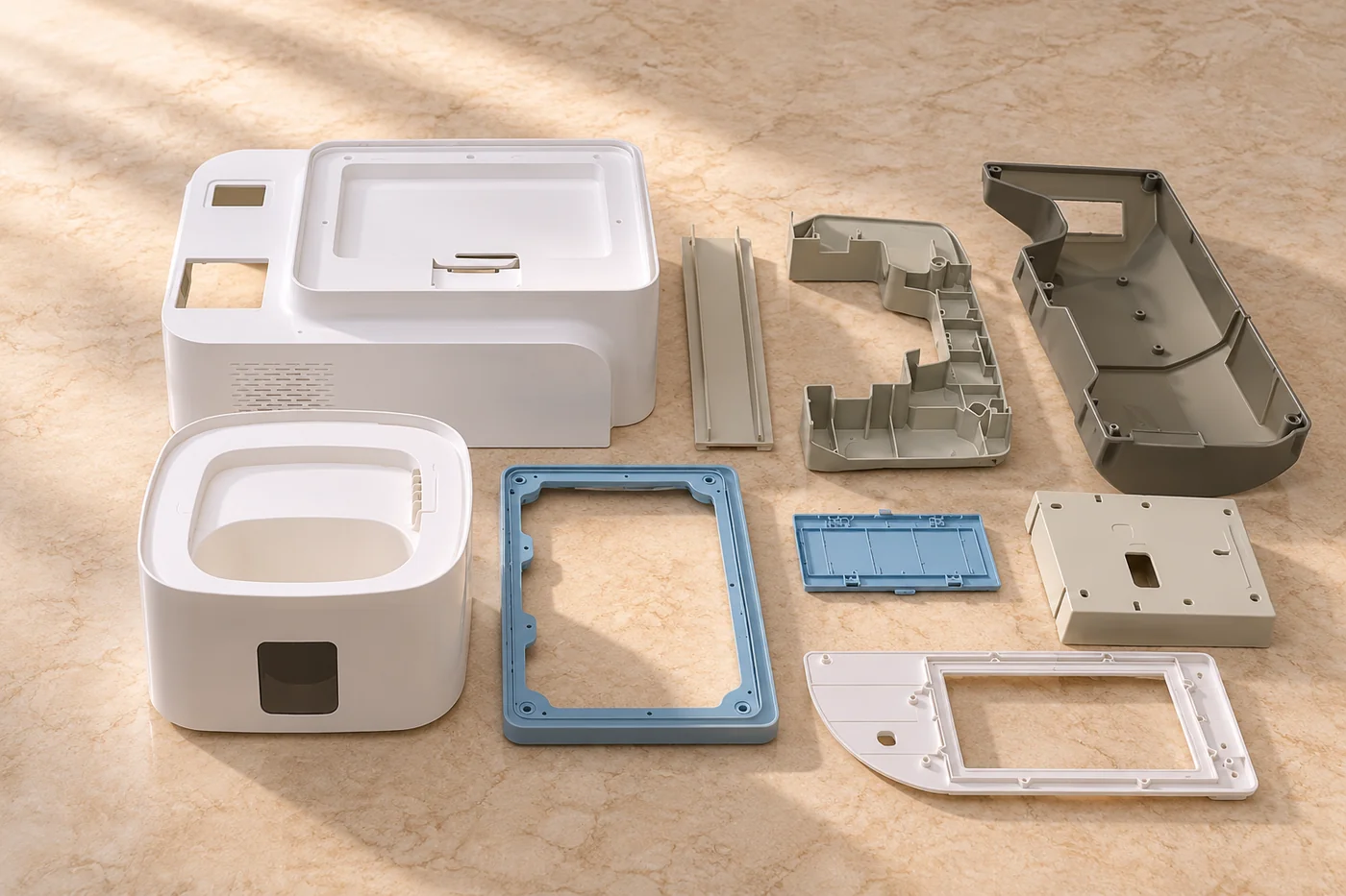
Separate preparation, individual operations, finishing and required trials. Keep open material or interface inputs visible before the development scope is agreed.
Technical notes
Show the two material regions separately in the CAD package. Define which surface locates in the assembly and which provides grip, cushioning or flexible movement. Include insert details where the flexible material is cast around another component.
| Scope | Retain |
|---|---|
| Preparation | Current models and material pair |
| Manufacture | Defined prototype sequence |
| Acceptance | Required interface and function checks |
RELIA · YOUR NEXT PROJECT
Send the material-region models and interface requirements
Share the combined design, material targets, quantity and intended function. Add the required surface and interface checks. We can review the prototype route with the two-material relationship clearly defined.
Start with these project details
- Separate-region CAD and inserts
- Material targets and quantity
- Retention and intended function
- Surface and interface checks
Shuyuan Road, Qingdao, Shandong, China
