
CUSTOM MANUFACTURING · PROJECT REVIEW
Custom Carbon-Steel Connectors for Construction Machinery
Relia reviews carbon-steel connector castings around the features that transmit and locate the load. Define the grade, pin bores, contact faces and required checks so investment casting and CNC machining follow the same finished-component requirement.
RELIA · PRODUCT AND MANUFACTURING SUPPORT
Locate the connector in the machine
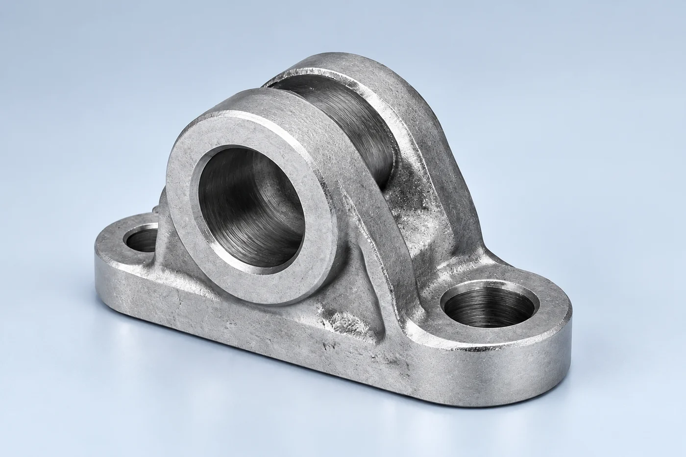
Relia's heavy-duty connector reference combines carbon-steel investment casting, CNC machining and shot- or sand-blasted surfaces. Relia's drawing-based scope connects the connector's sections and fillets to the machined bores and contact faces. Your engineering team can then identify the critical fit and required material properties without treating a general catalogue tolerance as the whole design specification.
| Your requirement | Relia product and service scope |
|---|---|
| Material | Specified carbon-steel grade |
| Route | Investment casting plus CNC machining |
| Surface reference | Shot blasting or sand blasting |
| Critical interfaces | Pin bores, load faces, fillets and retention features |
02 · DESIGN BASIS
Translate duty into drawing requirements
- Design requirement
- Specify the material and geometry for the intended duty.
- Critical zones
- Mark the interfaces needing manufacturing and inspection control.
Your design should establish the material and geometry needed for the required duty. Mark critical zones and interfaces so we can review the manufacturing and inspection scope.
Technical notes
Use cast geometry for the body while machining pin bores, contact faces or threads where required. State the carbon-steel grade and any heat-treatment condition. A general carbon-steel label does not establish yield strength, toughness or suitability for a safety-critical connection.
MANUFACTURING ROUTE · FEATURES AND CONTROL
Carry the Load Path Through Casting and Bore Machining
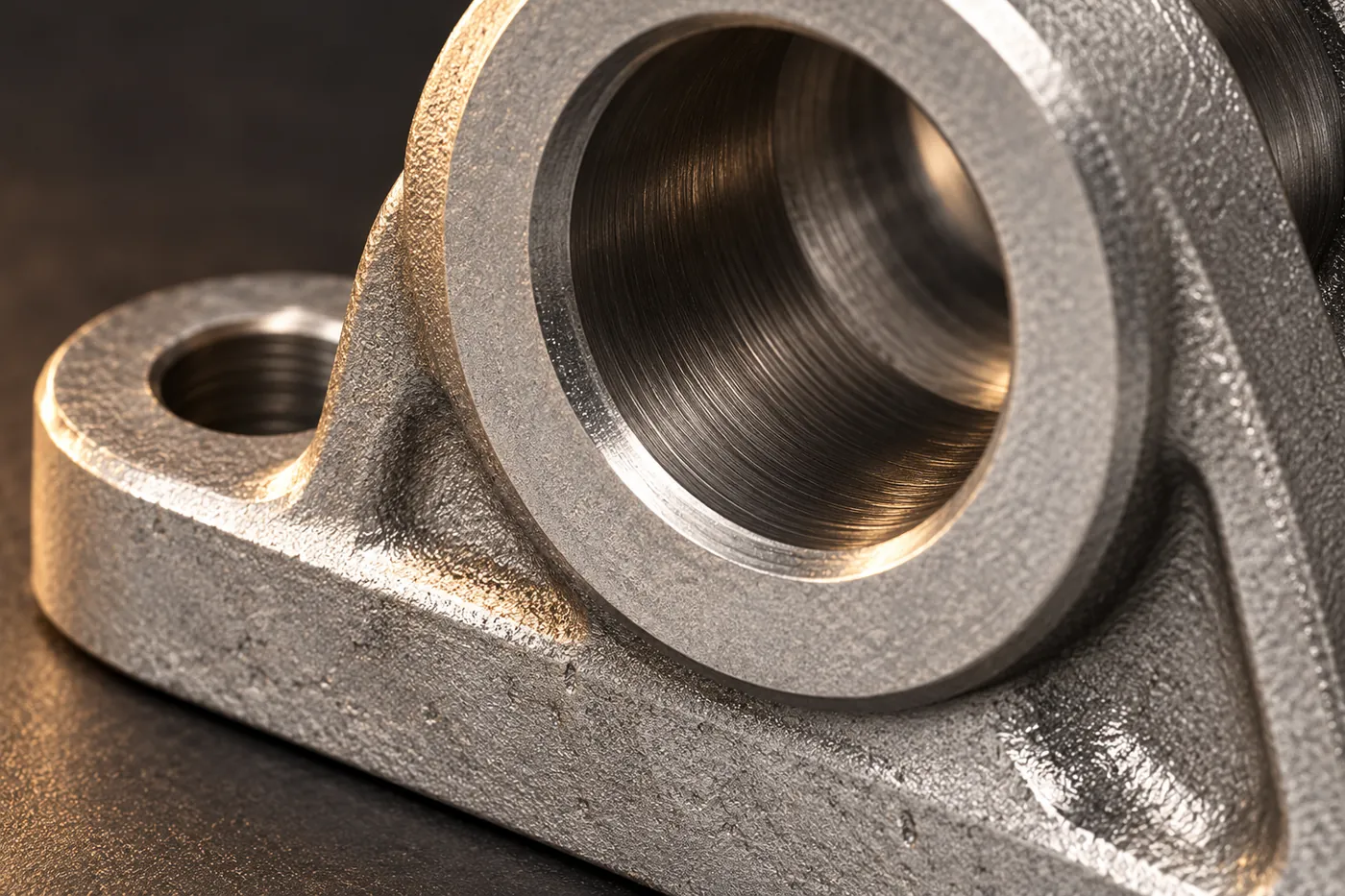
The investment pattern defines the connector body with transitions and stock around finished features. Casting, shell removal and gate cleaning establish the blank; any specified treatment follows the selected carbon-steel grade and property requirements. Relia's machining review sets the pin bores, bolt locations or contact faces from functional datums. Avoiding an abrupt section change or leaving an inaccessible bore is a design-and-process question, while dimensional and specified material checks establish the delivered component's acceptance.
- Review the connectorLoads, pin/bolt arrangement and section changes
- Cast the steel bodyPattern, mould and cleaned near-net shape
- Finish working interfacesBores, faces and required surface condition
- Check the ordered scopeDrawing features and specified property/NDT records
04 · PROCESS ROUTE
Plan casting and machining around the interfaces
- Cast body
- Review stock, transitions and machining access.
- Finished connection
- Establish bores and contact faces from defined datums.
Identify the stock allowance, locating datums and features requiring machining. The cast shape and finished connection should be reviewed as one manufacturing package.
05 · ACCEPTANCE
Inspect the zones that control the connection
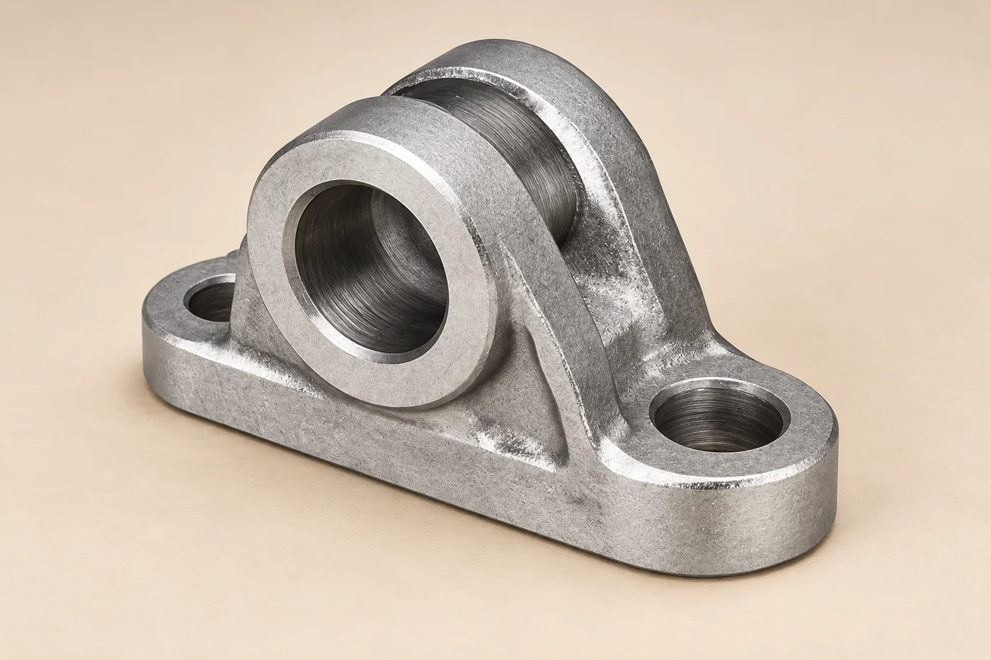
Check bore size, centre distance and wall relationships using nominated datums. Add mechanical-property or nondestructive tests where the design requires them, with acceptance criteria. The product's inspection description does not replace the customer's load validation or assembly approval.
06 · FIRST PARTS
Approve samples before working-service release
- Component sample
- Check the drawing requirements and trial assembly.
- Working release
- Retain the required machine-level functional approval.
Review the first component against the drawing and required trial assembly. The machine application retains its own functional and safety approval, with accepted deviations visible before release.
07 · ORDER CONTROL
Retain a clear connector package
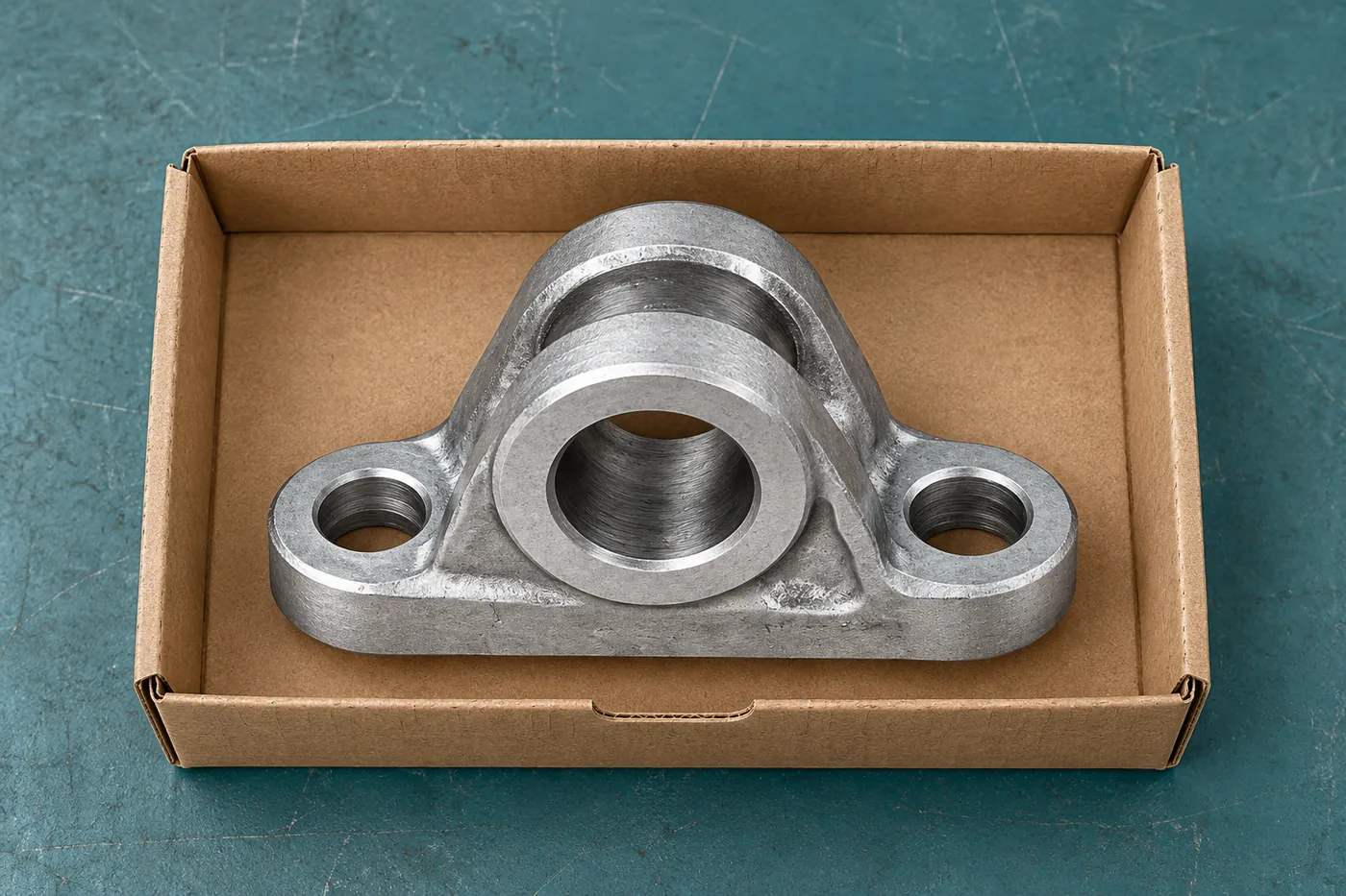
Keep the model, material, finished condition and required records together. State any included hardware expressly so the quotation and received component follow the same agreed scope.
Technical notes
Describe how the connector transfers load, the pin or bolt arrangement and the available assembly clearance. Include impact or cyclic loading in the design brief. The casting shape, fillets and section transitions need to support the approved design, not merely resemble an existing connector.
| Package | Retain |
|---|---|
| Technical | Current drawing and material |
| Manufacture | Casting, machining and finish |
| Acceptance | Required checks and release basis |
RELIA · YOUR NEXT PROJECT
Share the connector drawing and machine-interface requirements
Send the model, material specification, quantities and relevant assembly context. Highlight critical features and required checks. We can review the investment-cast and machined component scope with your project team.
Start with these project details
- Model and material specification
- Pin and mating-interface drawing
- Quantity and service context
- Critical-feature and approval checks
Shuyuan Road, Qingdao, Shandong, China
