
CUSTOM MANUFACTURING · PROJECT REVIEW
Custom Mounting Plates and Brackets for Automation Equipment
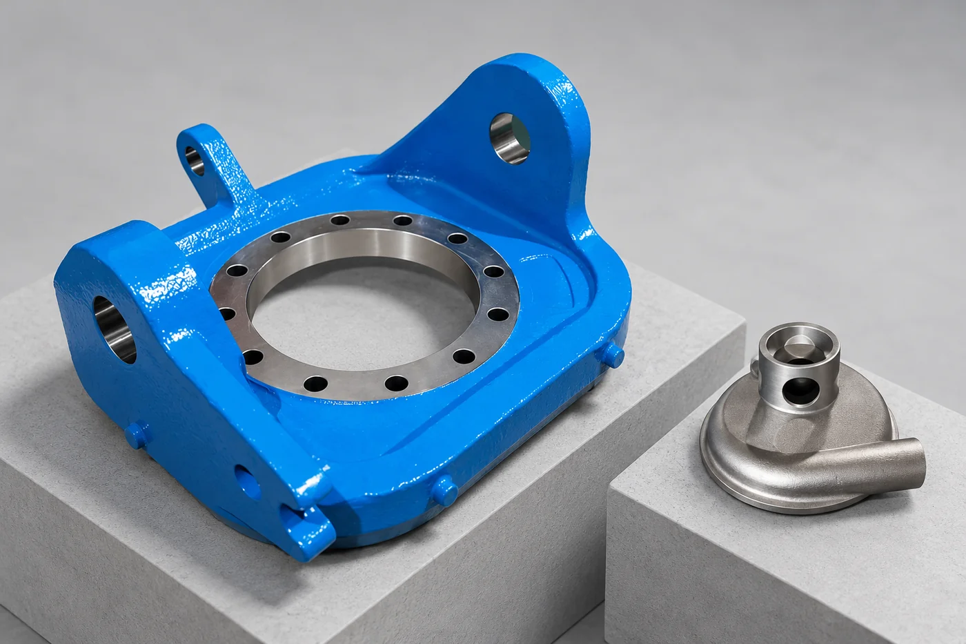
A mounting part may support a load, locate a mechanism or allow adjustment. Relia reviews those functions before the casting and machining scope, so the material, faces, holes and slots match the equipment's actual requirements.
RELIA · PRODUCT AND MANUFACTURING SUPPORT
Organise the parts around the equipment
Relia's stainless bracket reference lists 304/316 investment casting with machining and polishing; the aluminium bracket range supports custom CNC dimensions and colours. Relia connects these options to your mounting pattern, adjustment slots and locating features. That lets your team reserve close machining for the interfaces that control alignment while keeping the remainder practical to manufacture.
| Your requirement | Relia product and service scope |
|---|---|
| Stainless option | 304/316 investment casting, machining and polishing |
| Aluminium option | Custom CNC-machined bracket and specified colour |
| Key definition | Support versus precision locating function |
| Feature controls | Face relationship, pin bores, slots and bolt pattern |
02 · MANUFACTURE
Choose material and route for the individual part
- Individual requirement
- Specify the grade, geometry and delivered condition by part.
- Suitable route
- Compare casting and machining against that drawing.
Stainless casting and machined mounting-part references offer different starting directions. We review the selected grade, geometry and delivered condition against the actual drawing.
Technical notes
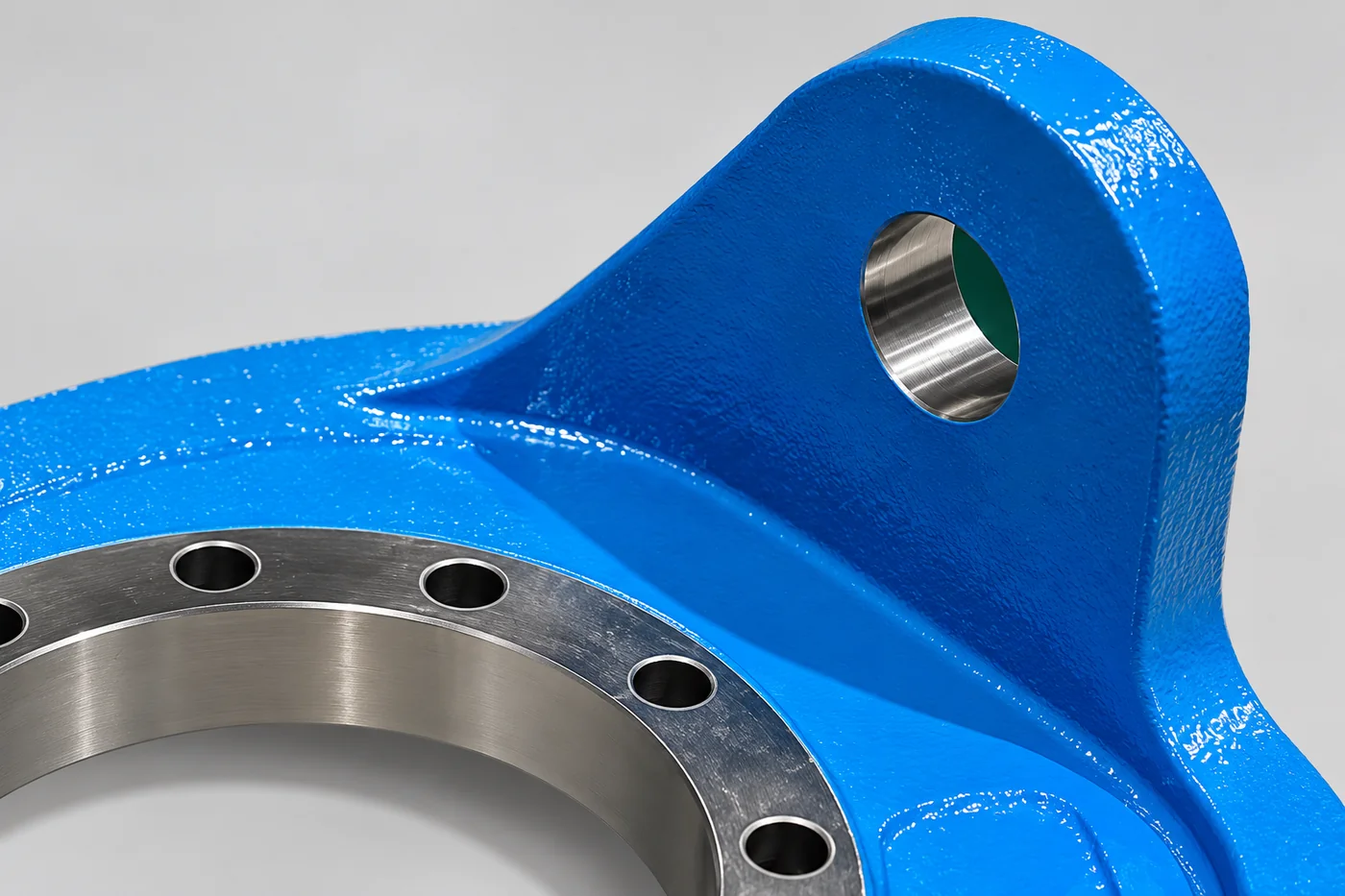
Our cast stainless bracket lists CT4–9 fields, while the finished holes and locating surfaces need their own drawing limits. Avoid applying a very close tolerance to the whole casting when only a pin bore controls alignment. Mask or finish machine controlled areas where coating changes fit.
MANUFACTURING ROUTE · FEATURES AND CONTROL
Separate the Support Shape From the Locating Features
An investment-cast bracket can carry ribs, offsets and transitions in its near-net body, while a machined plate may suit a simpler early design or different quantity. Relia's route review identifies the stable reference face and the holes, slots or pin bores located from it. Machining then establishes these features, followed by deburring and the specified polish or coating. Finishing must preserve face contact and fit, particularly where a dowel or sensor location carries more precision than the supporting body.
- Define the bracket's jobSupport, adjustment or precision location
- Select the starting shapeCast body or machined plate
- Finish the datumsFaces, slots, pin bores and mounting holes
- Approve the fixture fitAlignment, fastener access and finish
04 · FINISHING
Separate functional and visible surfaces
- Functional surface
- Mark locating faces, threads and supporting interfaces.
- Visible surface
- Define appearance and any required masking separately.
Identify the supporting faces, threads and locating features that need dimensional control. Define the visible finish independently, including any masking needed at the functional interfaces.
05 · FIRST PARTS
Approve the mounting relationship before installation
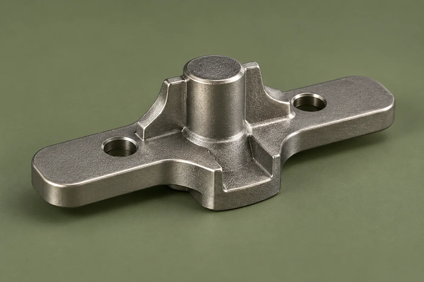
Inspect the locating relationship, mounting-face contact and access for fasteners. The listed one-piece minimum and 40–45-day reference belong to the stainless item, not every bracket. Approve the sample's fit and finish before freezing the repeat-production drawing.
06 · IDENTIFICATION
Keep similar mounting parts distinct
- Variant geometry
- Treat changed hole positions as distinct part definitions.
- Controlled identity
- Retain part numbers, revisions and finish references.
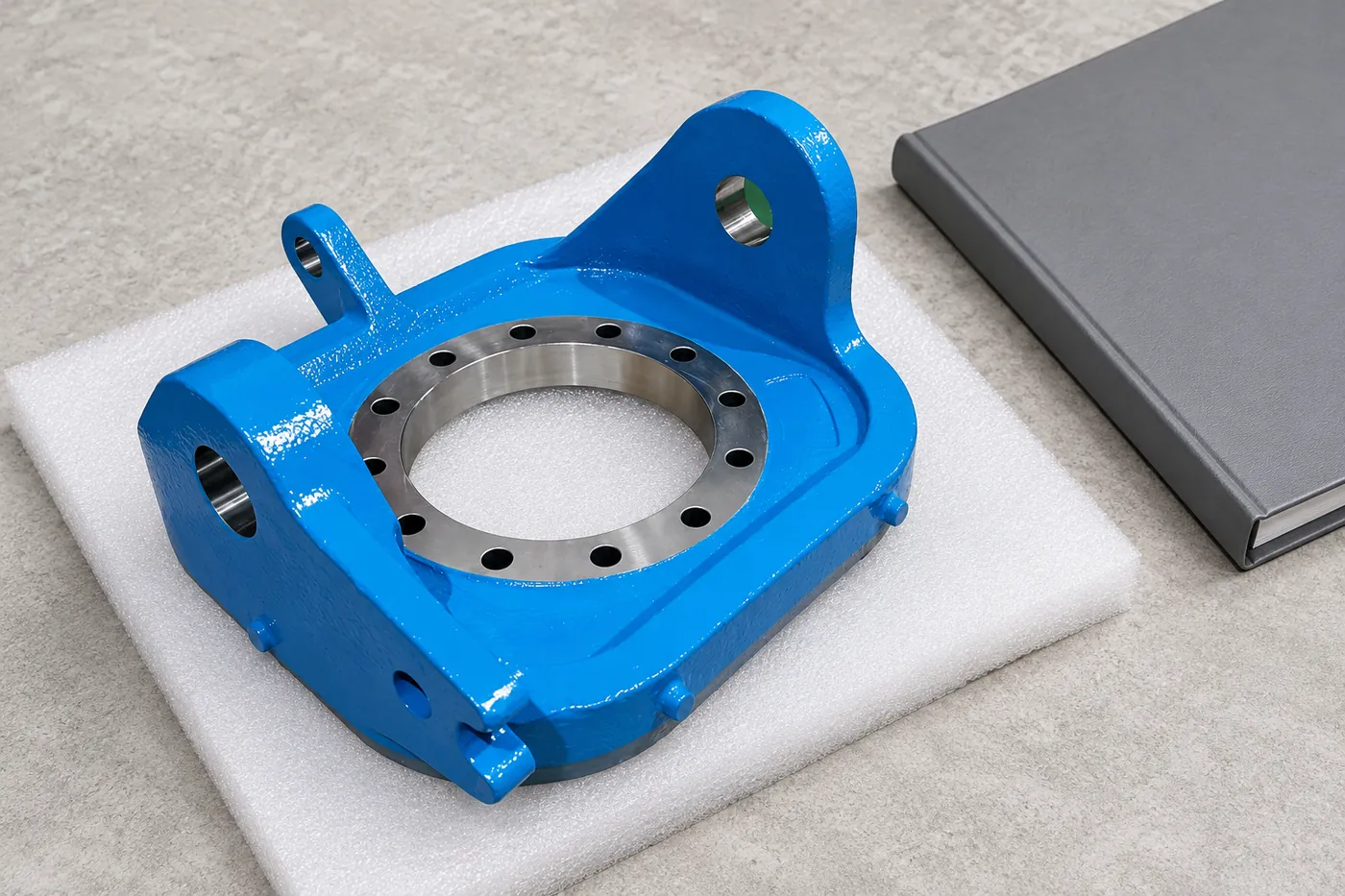
A small change in hole position can define a different component. Retain part identity, revision and approved finish references across the supplied mounting group.
07 · ORDER CONTROL
Retain the package at part level
A coordinated quotation should still identify each component and its included work. Keep open inputs and accepted changes connected to the drawing they affect.
Technical notes
Show the equipment datum, mounting pattern and adjustment range. Identify slotted holes, locating pins and the surfaces that carry load. A bracket intended only for support has different requirements from one that also locates a sensor or a precision motion component.
| Record | Retain |
|---|---|
| Drawing | Part and revision |
| Scope | Material, operations and finish |
| Approval | Accepted checks and deviations |
CONNECTED BUYING GUIDES
Continue with the next project decision
Follow the related component and purchasing guides, or open the catalogue reference to carry this requirement into a specific project enquiry.
RELIA · YOUR NEXT PROJECT
Share the mounting drawings with the assembly references
Send the component list, current drawings, materials and quantities. Identify common datums and the finished interfaces your equipment uses. We can review the package and its part-level quotation requirements.
Start with these project details
- Component list and drawings
- Material and quantity by item
- Locating datums and interfaces
- Finish and acceptance requirements
Shuyuan Road, Qingdao, Shandong, China
