
CUSTOM MANUFACTURING · PROJECT REVIEW
Custom Aluminum Motor Housings with Machined Bearing Locations
Relia reviews aluminium motor housings around the interfaces that locate the assembly. Bring bearing bores, shoulders, end faces and cover relationships together, then define the casting, machining and acceptance scope from that drawing.
RELIA · PRODUCT AND MANUFACTURING SUPPORT
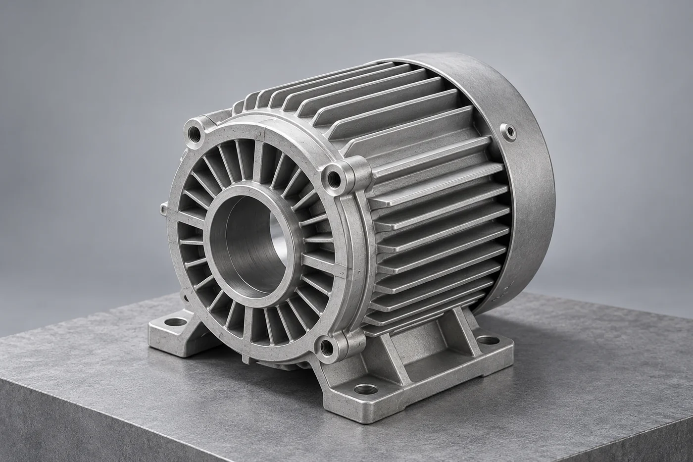
Identify the housing within the motor assembly
Relia's motor-housing description includes customized wall thickness, raw-material control, treatment review and finished inspection. Relia connects those requirements to the stator location, bearing seats and mating end covers. This is useful for motor OEMs that need a housing supplied to a defined mechanical interface instead of selecting a similar-looking shell by size alone.
| Your requirement | Relia product and service scope |
|---|---|
| Material | Aluminium housing reference |
| Geometry | Wall thickness and dimensions customized to drawings |
| Locating features | Bearing bores, shoulders and end-cover interfaces |
| Inspection scope | Raw material, relevant treatment and finished features |
02 · CRITICAL INTERFACES
Define the bearing and locating relationships
- Locating scheme
- Relate bores and end faces to the operating axis.
- Drawing control
- Define the adjoining-part interfaces and required checks.
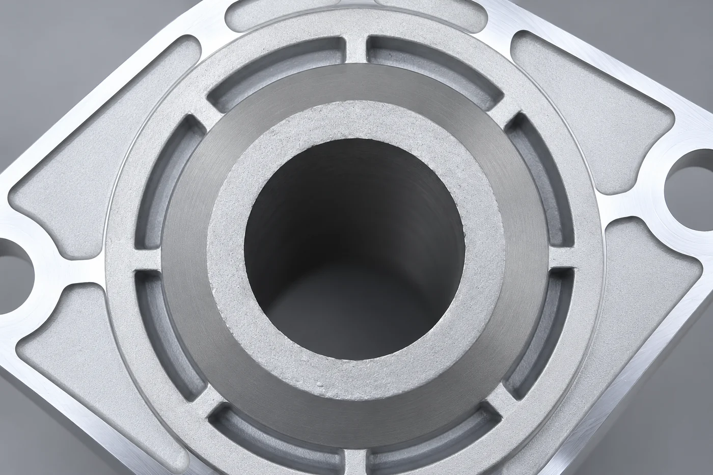
Bring the bore sizes, end faces and operating centreline into one datum scheme. Include the relationships that your assembly uses to locate adjoining parts. We review the finished interfaces and their inspection requirements from that scheme rather than treating a single tolerance as a description of the whole housing.
Technical notes
Locate the bearing bores from a consistent datum system. Their coaxial relationship, shoulders and end-face runout can affect assembly even when each diameter measures correctly. Machining allowance and fixture access need to be reviewed together with the housing's cast ribs and wall transitions.
MANUFACTURING ROUTE · FEATURES AND CONTROL
Create a Stable Datum Path Through the Motor Housing
The cast route forms the housing body and its cooling or mounting geometry, with stock retained for locating features. Relia's machining review establishes the bearing-seat arrangement, shoulders and end-cover registers from the nominated datums. Controlling these relationships avoids accepting two individually correct diameters whose axes or axial positions do not suit the rotor assembly. Finishing protects the exterior while preserving fits and contact areas. A cooling jacket, if included in the design, needs its own passage and leakage requirements.
- Define the cast bodyWall, mounting and cooling geometry
- Establish datumsBearing axis and end-cover relationship
- Finish locating featuresBores, shoulders, registers and faces
- Check the motor interfaceMeasurements and relevant trial assembly
04 · FINISH MACHINING
Set the operation sequence around the datums
- Operation sequence
- Establish and inspect the finished bores and faces.
- Final condition
- Account for treatment or coating at critical dimensions.
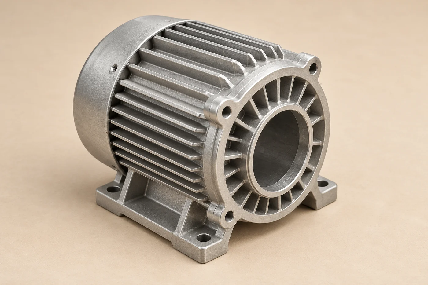
A useful route explains how the finished bores and faces are established and checked. Identify any treatment or coating that affects the final dimensions. We review the proposed sequence with the required material condition so that the delivered interfaces correspond to the accepted drawing.
05 · ACCEPTANCE
Inspect the relationships used by the assembly
Inspect the specified bores and faces after operations that can alter them. Add trial assembly, leak checks for a cooling jacket or other functional checks only where relevant to the design. Flexible scheduling in the catalogue is not a declared motor power rating or a fixed delivery commitment.
| Check area | Decision supported |
|---|---|
| Bores and faces | Finished geometry meets the drawing |
| Relative position | The locating relationships are controlled |
| Surface condition | Assembly and handling requirements are met |
| Trial assembly | The defined mating review is accepted |
06 · MATING COMPONENTS
Keep the end-cover interfaces on the same revision
- Mating covers
- Keep registers and fastening patterns consistent.
- Linked revisions
- Approve the housing and cover relationship together.
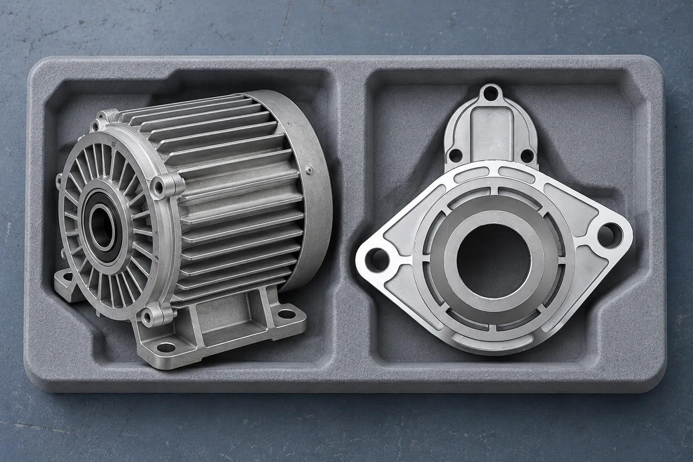
The housing and cover drawings need to describe the same registers, holes and locating relationships. Keep their approved revisions linked, even when the parts are ordered separately. We can review the component scope with those references available while your team retains the assembly approval for the intended combination.
07 · PROGRAMME CONTROL
Retain the accepted route for the next release
Keep the selected alloy, cast form, machining definition and inspection basis together after sample approval. A later tooling or material proposal should identify the features it may affect. Both teams can then assess the change against the same accepted housing and assembly requirements.
Technical notes
Identify stator location, bearing-seat arrangement, cooling features and the mating end covers. State which interfaces locate the rotor axis and which allow the intended assembly movement. This avoids treating every round surface as a bearing fit or every fin as an interchangeable cooling feature.
CONNECTED BUYING GUIDES
Continue with the next project decision
Follow the related component and purchasing guides, or open the catalogue reference to carry this requirement into a specific project enquiry.
RELIA · YOUR NEXT PROJECT
Share the housing and adjoining-interface drawings
Send the housing model, bearing and mounting requirements, relevant cover drawings and quantities. Add the material condition, finish and records your assembly approval needs. We can review the cast and machined component scope with the full locating relationship visible.
Start with these project details
- Housing model and cover drawings
- Bearing and mounting requirements
- Material condition and finish
- Quantities and inspection records
Shuyuan Road, Qingdao, Shandong, China
