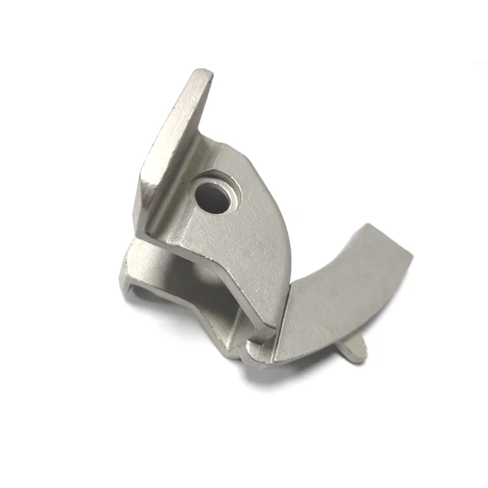
OEM Aluminum Machinery Castings, Custom Lost-Wax Investment Casting and Stainless Steel Inquiries
Let’s define your requirement
Send a product link, drawing or short brief. We’ll work through the details with you.
- Confirm the specificationGrade or model, size and intended use.
- Define your orderQuantity, finish or configuration, and samples.
- Agree the quotation scopeIncluded work, key checks and delivery needs.
-
Surface FinishSandblasted
-
Product nameCustom Aluminum Stainless Steel Investment Casting Lost Wax
-
MaterialAluminumApplicationMachinery
-
Surface treatmentSand BlastingProcessLost wax
-
ServiceOEM SeriviceCertificationISO9001:2015
-
SizeCustomer's 2D/3D DrawingStandardGB ASTM AISI DIN BS
-
Drawing File3D/CAD/DWG/PDF
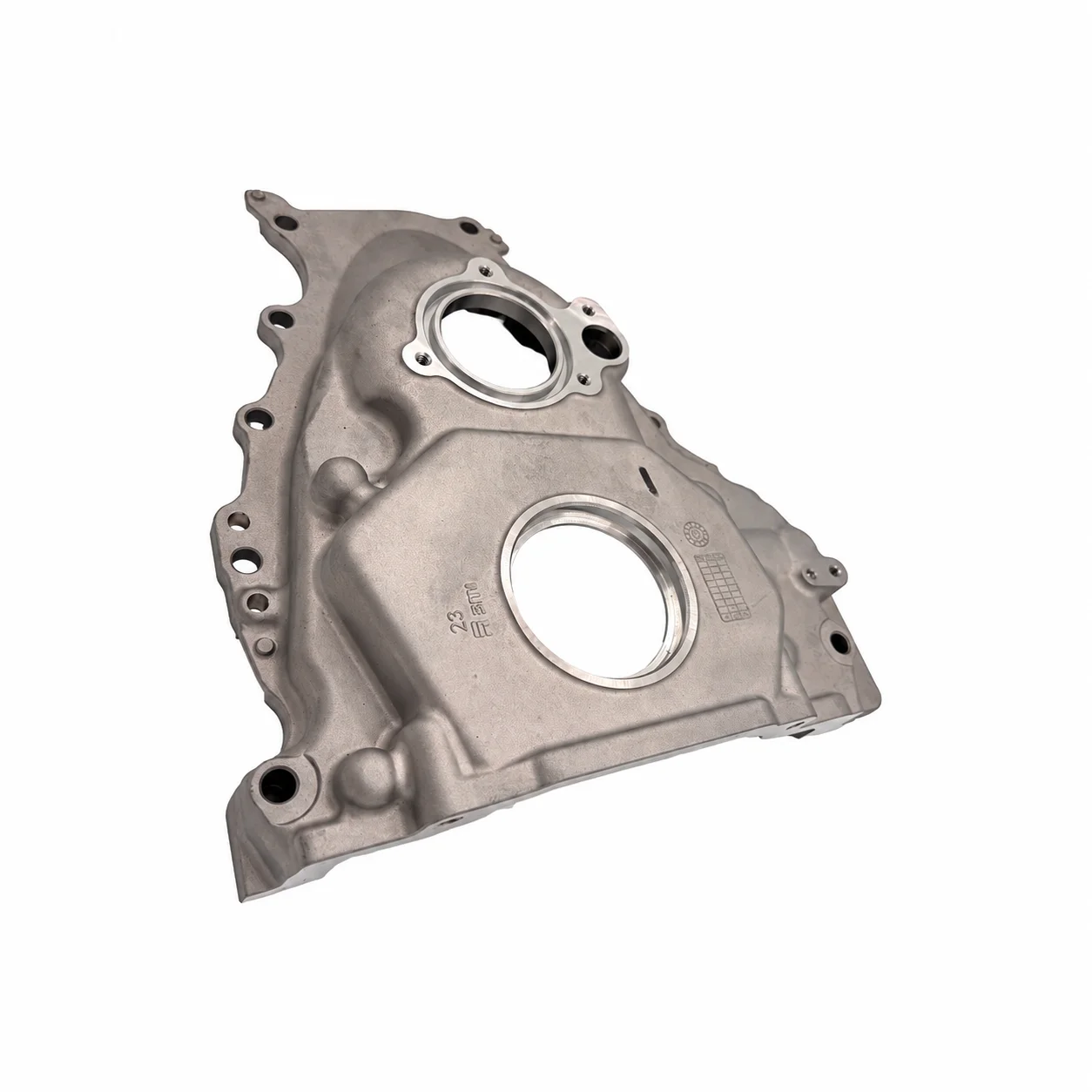
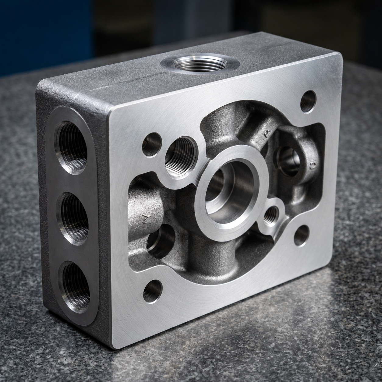
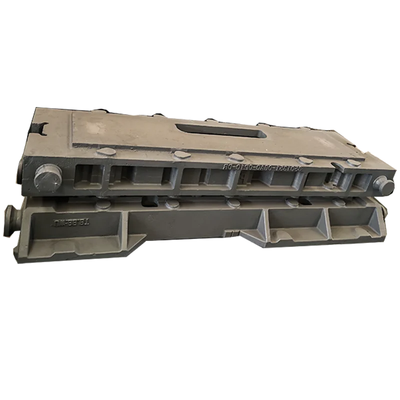
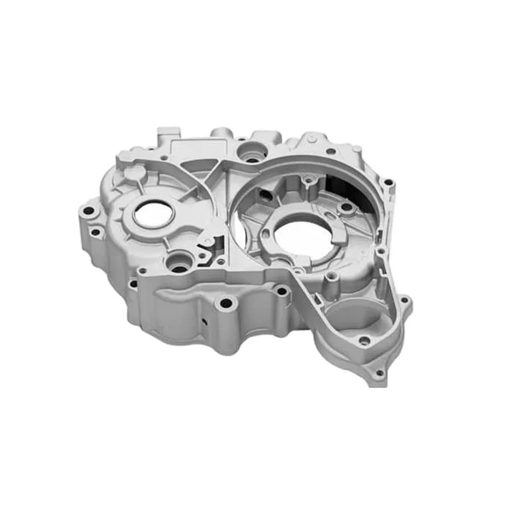
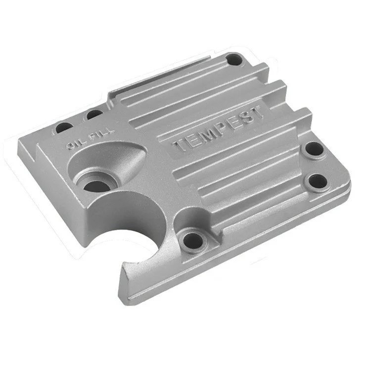
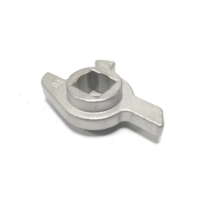
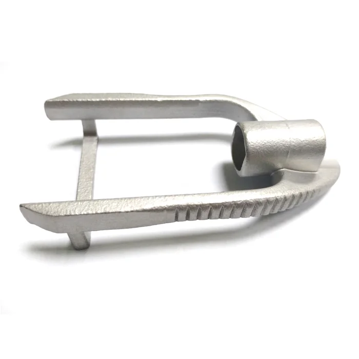
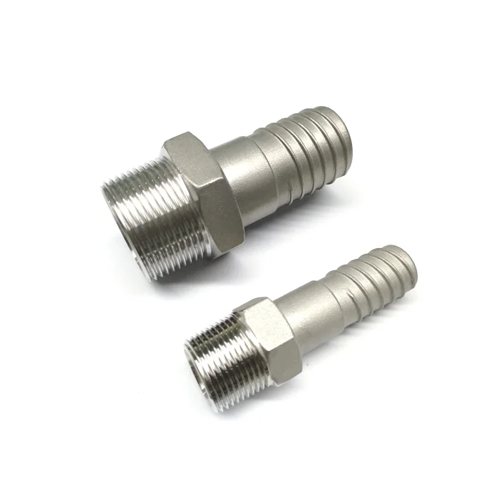
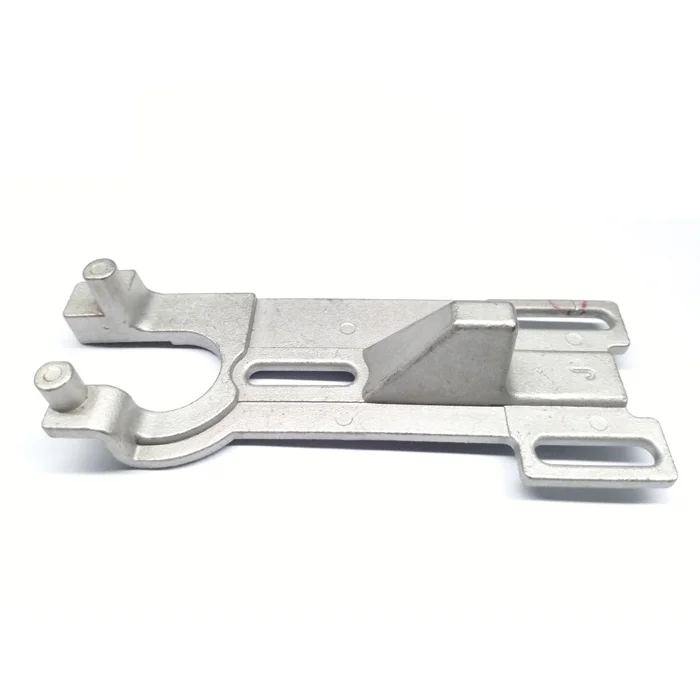
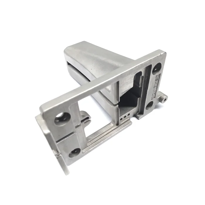
Aluminum machinery components are available through a custom OEM lost-wax investment-casting direction. Sand blasting is the surface treatment, and the size follows the customer's 2D/3D drawing. A stainless-steel casting direction can also be discussed separately for the chosen material and component.
Machinery function and material selection
Start with the component's role in the machine and the material requirement that belongs to it. Select the aluminum alloy or define the stainless-steel alternative for that particular design. The cast geometry and its mating relationships should be considered with the machinery function, giving the custom inquiry a specific part to address.
Drawing dimensions and sand-blasted surfaces
The customer's drawing defines the size rather than a fixed catalogue dimension. Identify the surfaces and interfaces that need dimensional acceptance, then agree tolerances and the required sand-blasted condition for the component. Relating the surface request to the geometry keeps visible areas and functional interfaces within the same design discussion.
Standard requirements and drawing inputs
GB, ASTM, AISI, DIN and BS are standard families to select from for the actual material and part requirements. Define the applicable requirement alongside the drawing and component acceptance rather than treating a family name as a completed specification. Drawing inputs include 3D, CAD, DWG and PDF directions. Use the representation that communicates the cast form, dimensions and mating geometry for the OEM review, with the selected material and surface condition carried through the same inquiry.