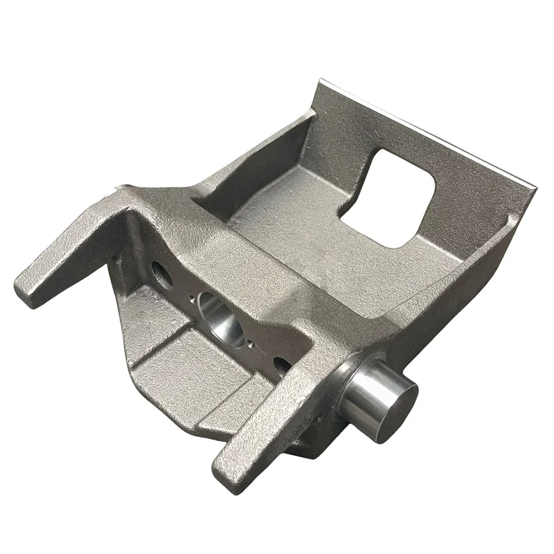
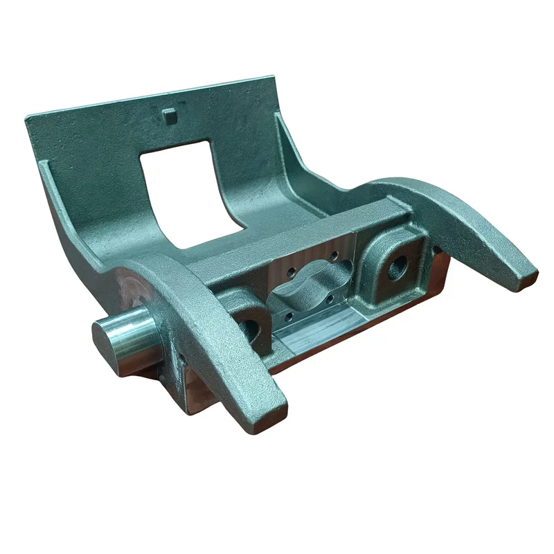
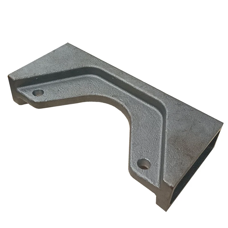
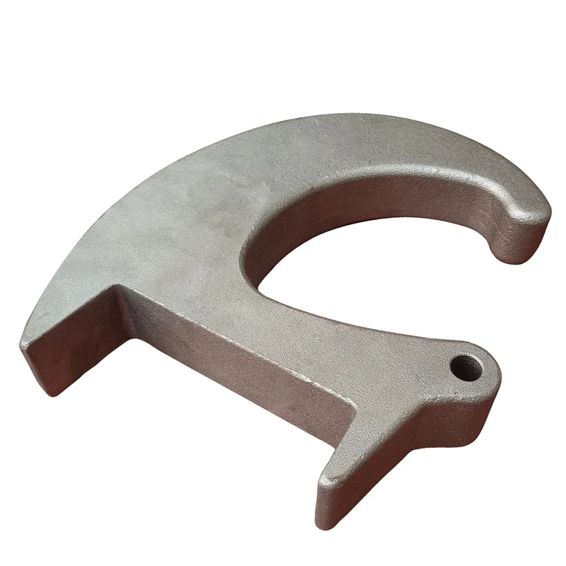
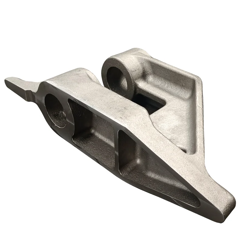
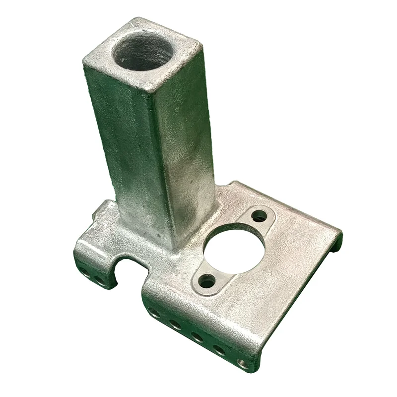
Custom Shell-Molding Casting with CNC Machining, Quench and Temper, Shot Blasting and Assembly
Let’s define your requirement
Send a product link, drawing or short brief. We’ll work through the details with you.
- Confirm the specificationGrade or model, size and intended use.
- Define your orderQuantity, finish or configuration, and samples.
- Agree the quotation scopeIncluded work, key checks and delivery needs.
-
Surface FinishShot Blasted
-
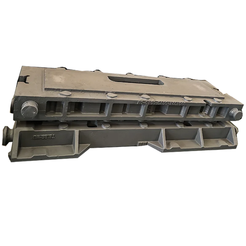
NameCustomized Casting Shell Molding Process
-
AppplicationOtherProcessShell Mouding casting+CNC machined
-
Heat TreatmentQuench and temper by 2 set mesh belt furnacesSurface TreatmentShot blasting+Assembling
-
Machining Facility50+ Machining centers,80+ CNC machinesInspectionMT/UT/RT/100% visual+100%gage/CMM
-
StandardASTM. AISI. DIN. BS. JIS. NF. AS.CertificationIATF16949/ISO14001
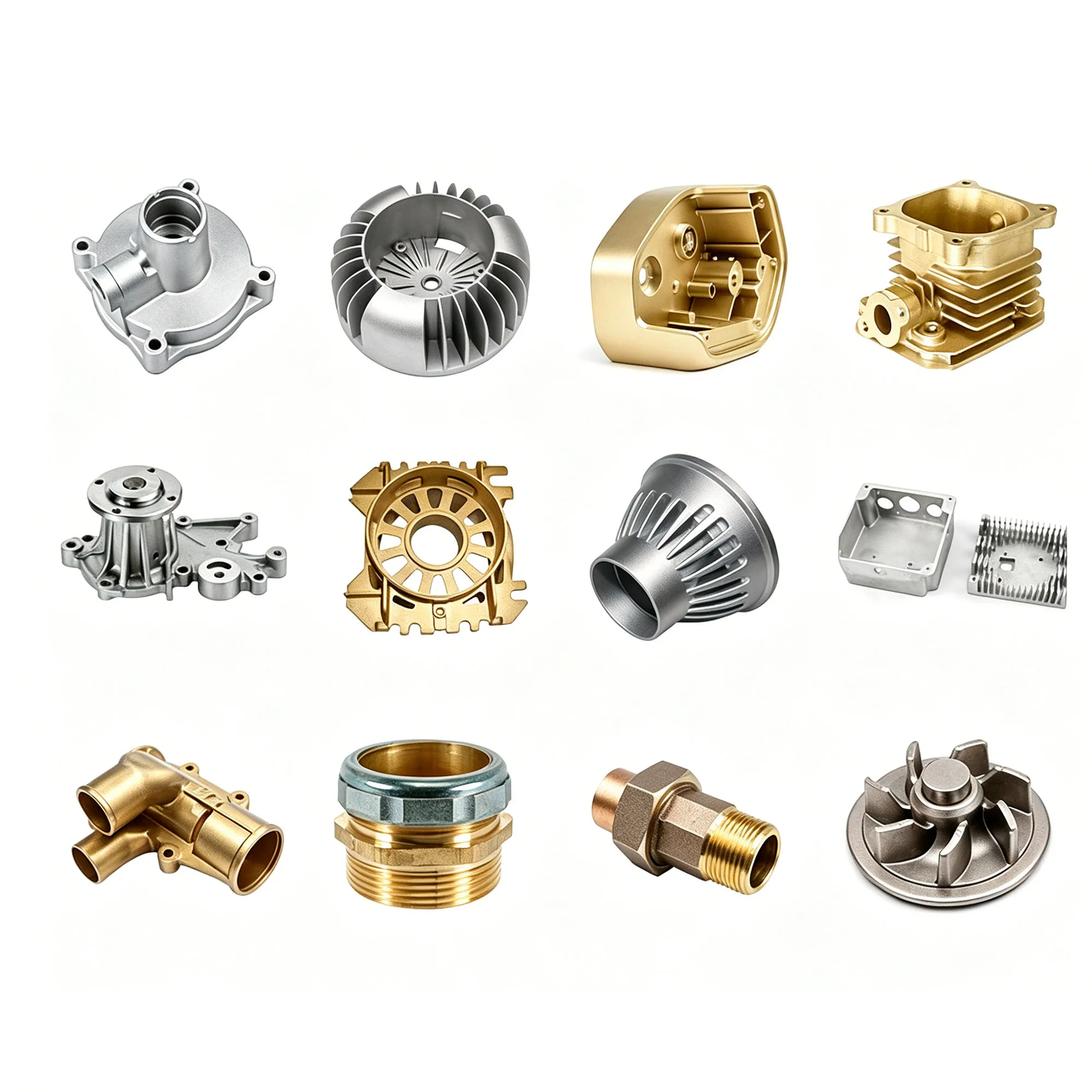
A customized shell-molding project can include the casting, CNC work, heat treatment and assembly scope required by the component. This process offering brings those operations into the project discussion, with inspection methods and the applicable material requirements agreed for the actual part.
Distinguish the cast form from CNC work
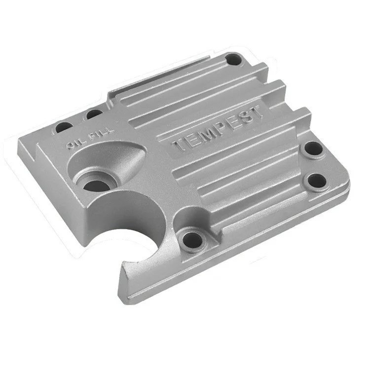
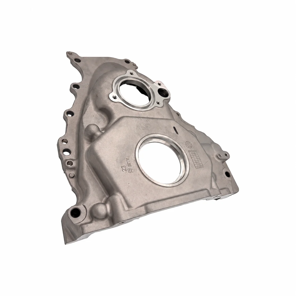
Shell-molding casting is combined with CNC machining. Define the component geometry and identify the areas requiring machining, keeping their accepted dimensions clear within the overall part drawing. The machining scope includes machining centers and CNC machines, while the proposal should still describe the work required for this component.
Give quench and temper a defined outcome
Quenching and tempering use two mesh-belt furnace sets within the stated treatment scope. Specify the material grade and the treatment outcome needed by the project, then agree how that condition is accepted. A treatment route should remain connected to the chosen material and component requirements.
Set the shot-blasting and assembly boundaries
Shot blasting and assembling are included in the service discussion. Identify the surfaces to be treated and the items or operations included in assembly, so the supplied condition is clear. This gives the component inquiry a specific finishing and assembly scope instead of assuming an undefined complete assembly.
Choose inspection methods and coverage deliberately
The inspection range includes MT, UT, RT and CMM, with 100% visual and 100% gauge inspection specified. Agree which methods and acceptance criteria apply to the part; the visual and gauge percentages should remain associated with those checks. Use the same component definition for machining, treatment and inspection decisions.
Identify the applicable material requirement
ASTM, AISI, DIN, BS, JIS, NF and AS requirements can be considered in the project brief. Select the exact material specification and revision relevant to the component, and confirm applicable IATF16949 or ISO14001 documentation if the order requires it.