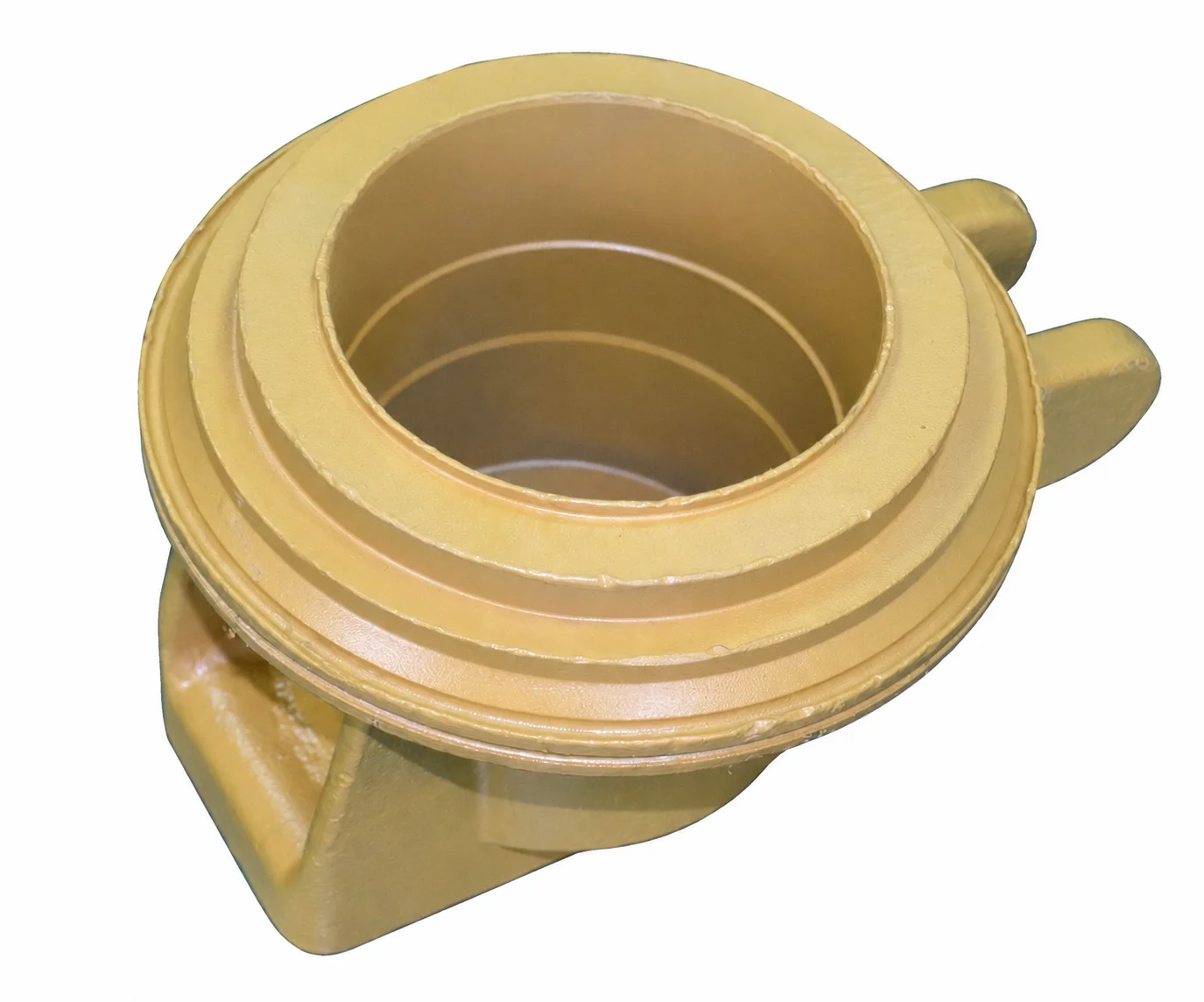
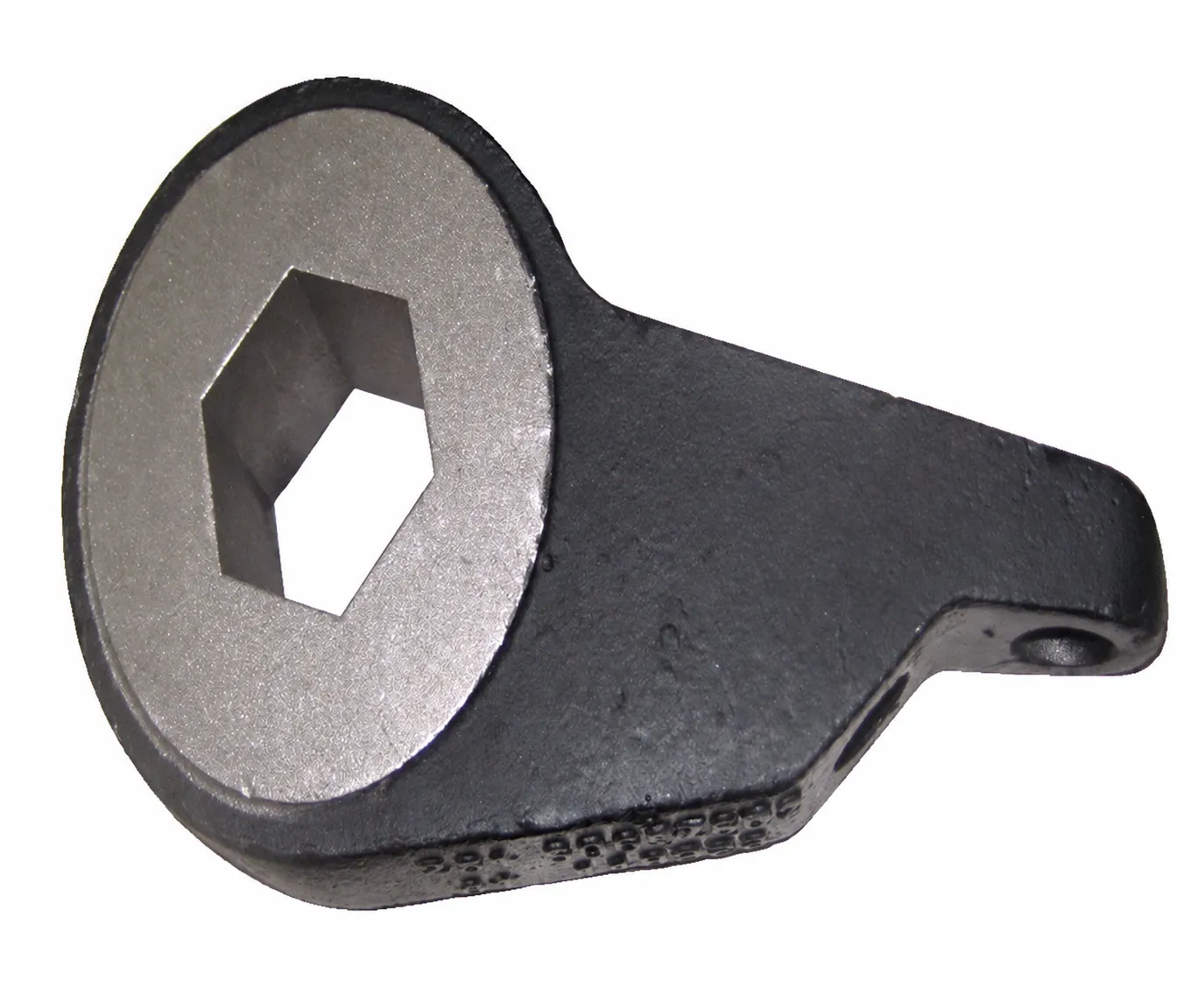
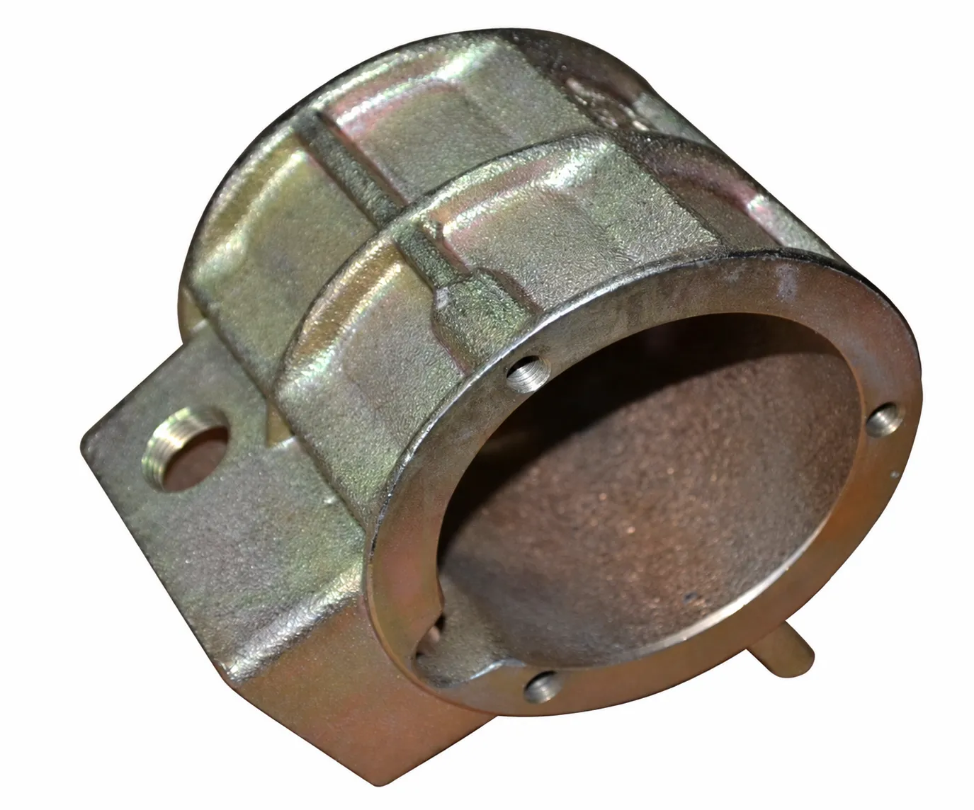
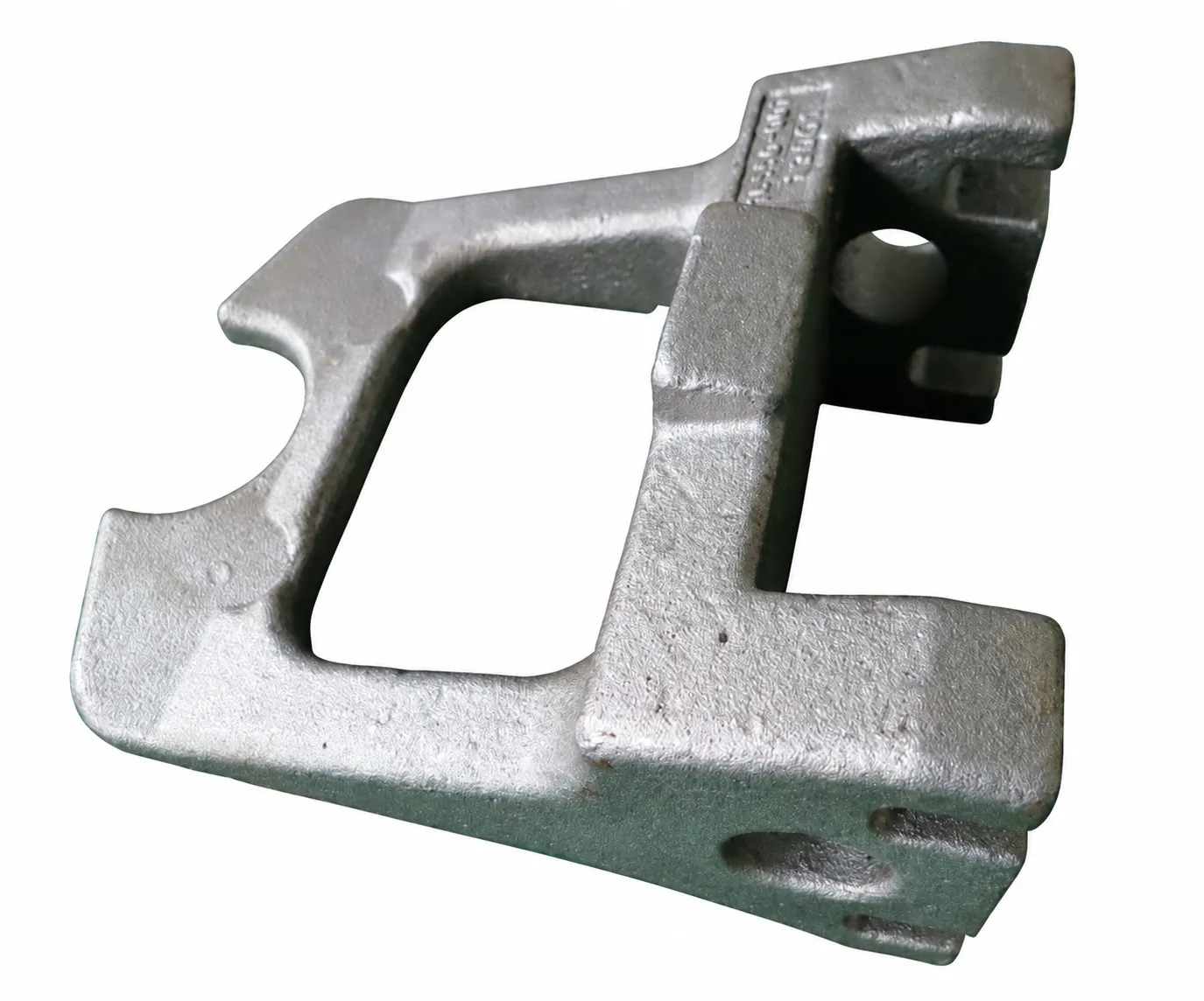
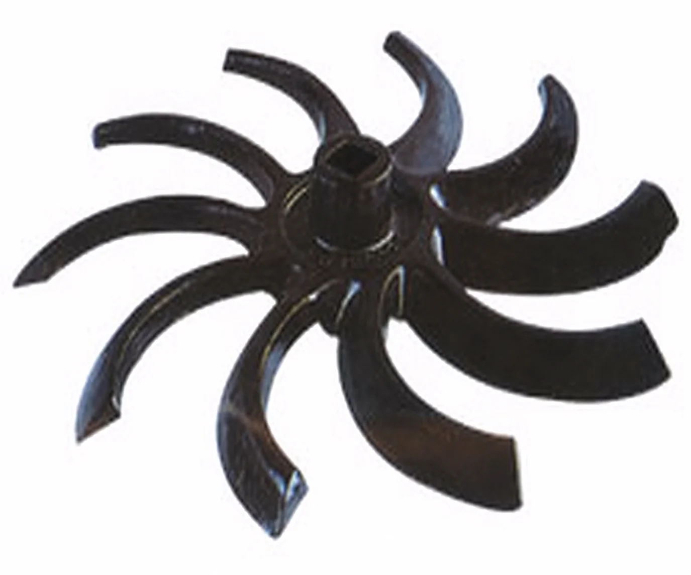
Steel Lost Wax Impeller Castings with CNC Machining and Quench-and-Temper
Let’s define your requirement
Send a product link, drawing or short brief. We’ll work through the details with you.
- Confirm the specificationGrade or model, size and intended use.
- Define your orderQuantity, finish or configuration, and samples.
- Agree the quotation scopeIncluded work, key checks and delivery needs.
-
Component FormImpeller / RotorSurface FinishShot Blasted
-
MaterialSteel
-
NameChina Lost Wax Impeller Casting CompanyKeywordslost wax company
-
ProcessLost wax investment casting+CNC machinedHeat TreatmentQuench and temper by 2 set mesh belt furnaces
-
Surface TreatmentShot blasting+AssemblingMachining Facility50+ Machining centers,80+ CNC machines
-
InspectionMT/UT/RT/100% visual+100%gage/CMMStandardASTM. AISI. DIN. BS. JIS. NF. AS.
-
CertificationIATF16949/ISO14001
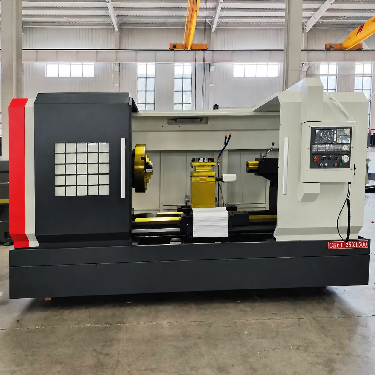
Steel impeller production combines lost wax investment casting with CNC machining and secondary treatment. Quenching and tempering use two mesh-belt furnaces, with shot blasting and assembly also available. The machining facilities include 50+ machining centers and 80+ CNC machines.
Set the grade and finished impeller condition
Select the steel grade and the particular requirements governing the impeller drawing. ASTM, AISI, DIN, BS, JIS, NF and AS are standard families for that review. Agree the heat-treatment condition and acceptance for quenching and tempering, then connect those requirements to the finished geometry and actual operating duty.
Coordinate machining, blasting and assembly
Identify the interfaces requiring CNC machining and the dimensional relationships that control assembly. Define the surfaces receiving shot blasting and their required final condition. Review the treatment and machining sequence against the drawing so that the casting, finished interfaces and assembled result share a clear acceptance basis.
Distinguish inspection objects and methods
The impeller inspection scope includes MT, UT and RT, together with 100% visual inspection and 100% gauge/CMM inspection. Agree the selected methods, inspection objects and acceptance criteria for the part. Define which records need to accompany the finished impeller and connect them to the material, treated condition and critical dimensions.
Match system scope to the project
IATF16949 quality-system and ISO14001 environmental-system scope can be reviewed for the manufacturing project. Keep those system requirements alongside the part-specific duty and inspection plan. Specify any needed rotation, balance, fluid-service or operating-performance acceptance for the impeller itself, with the applicable verification agreed before the final component is approved.