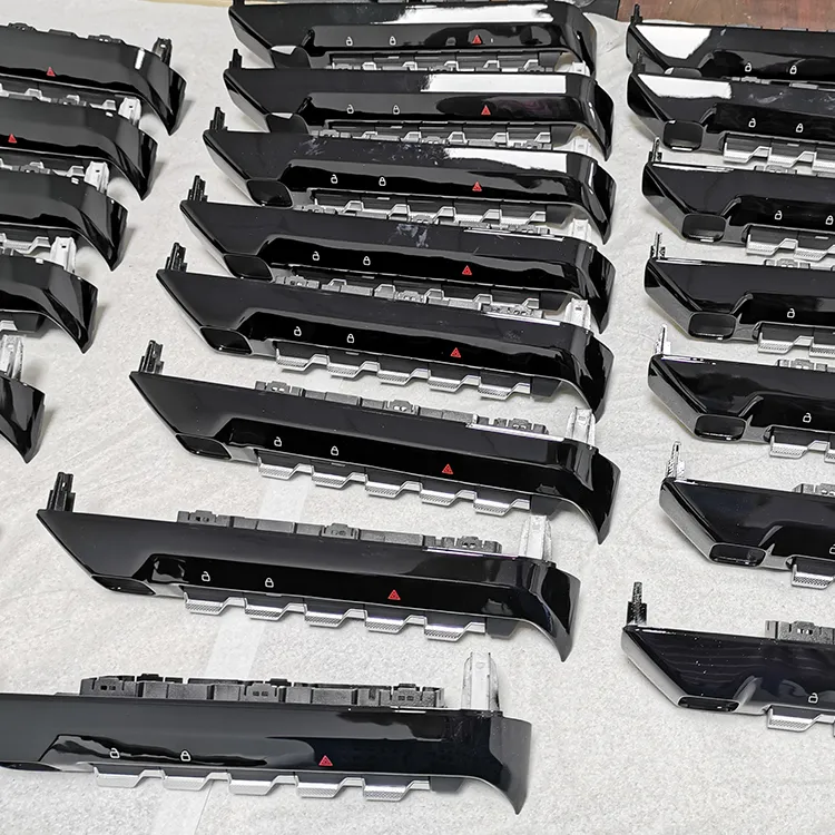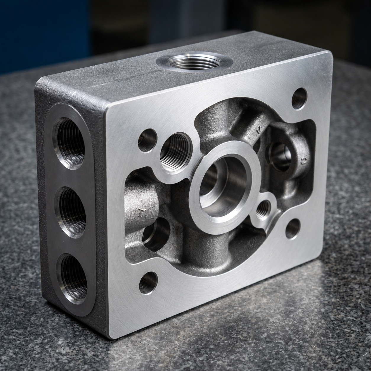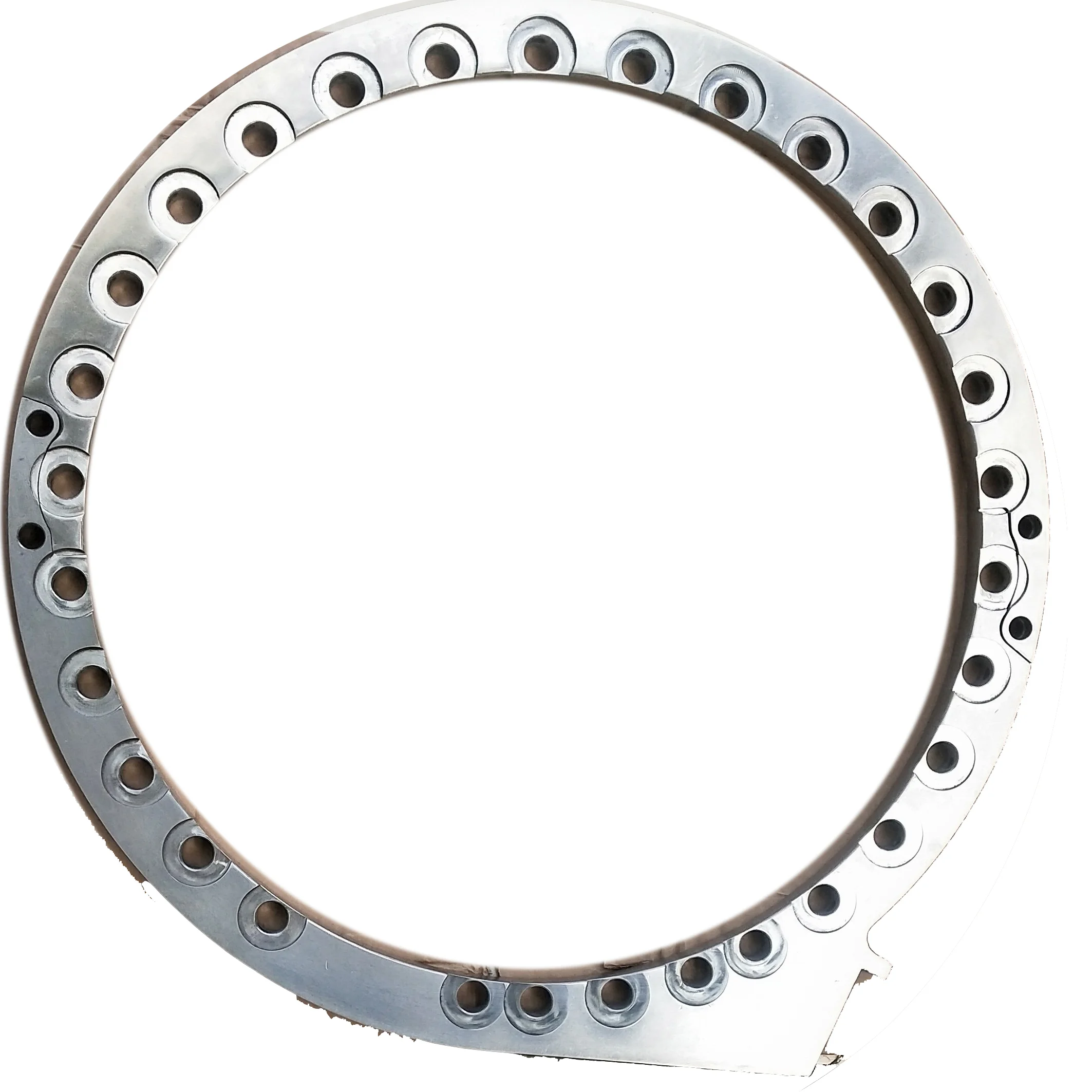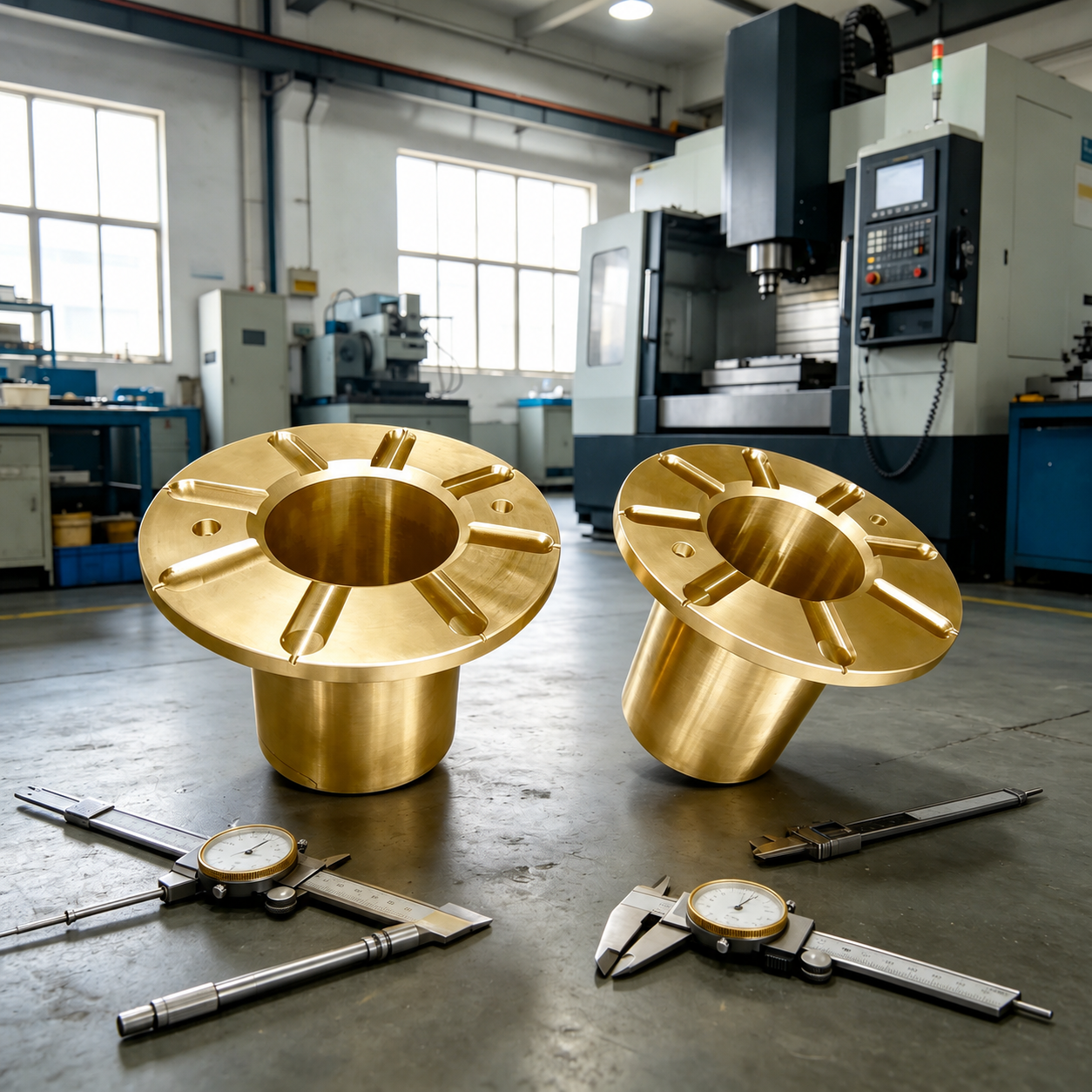
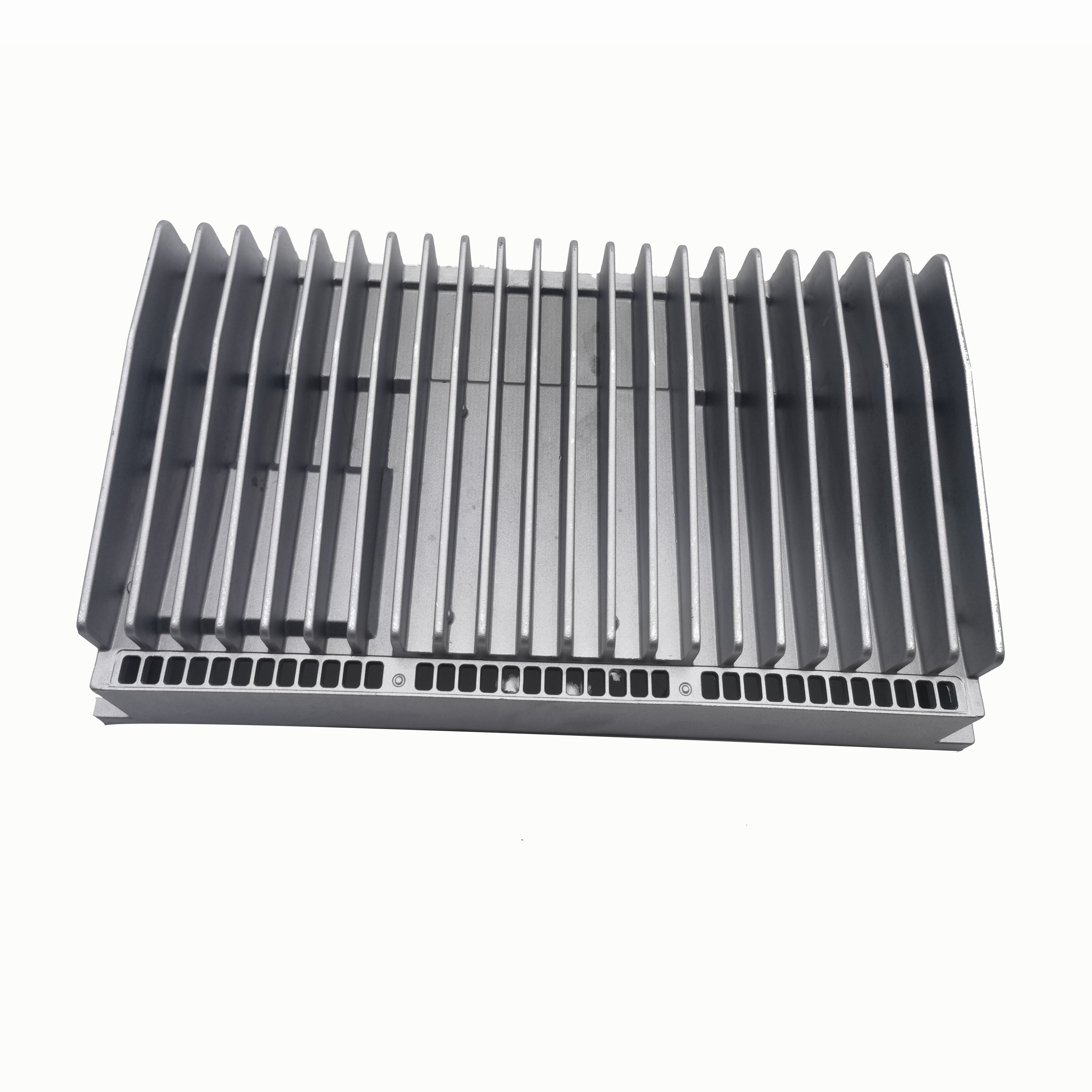
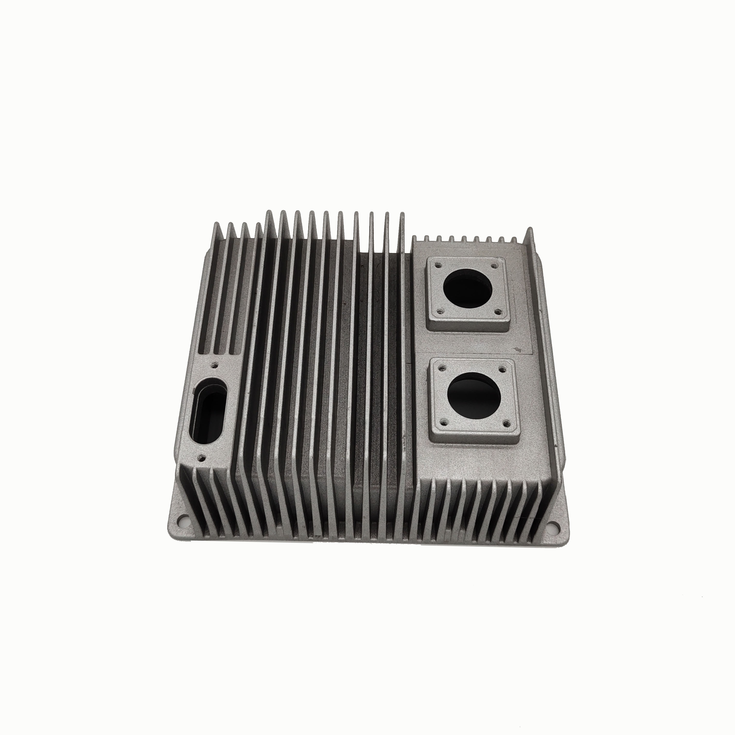
Precision Aluminum Machinery Parts Lost-Wax Investment Casting with CNC and Steel Enquiries
Let’s define your requirement
Send a product link, drawing or short brief. We’ll work through the details with you.
- Confirm the specificationGrade or model, size and intended use.
- Define your orderQuantity, finish or configuration, and samples.
- Agree the quotation scopeIncluded work, key checks and delivery needs.
-
Surface FinishPolished
-
MaterialAluminum
-
Surface treatmentPolishingProduct nameInvestment Casting
-
ApplicationMachinery PartsProcessCasting. Deburring .Drilling .threading
-
ServiceSamplesLead Time10-15 Days
-
MachiningCnc Machining CentreDrawing format2D/(PDF/CAD)3D(IGES/STEP)
-
ColorCustomized Color
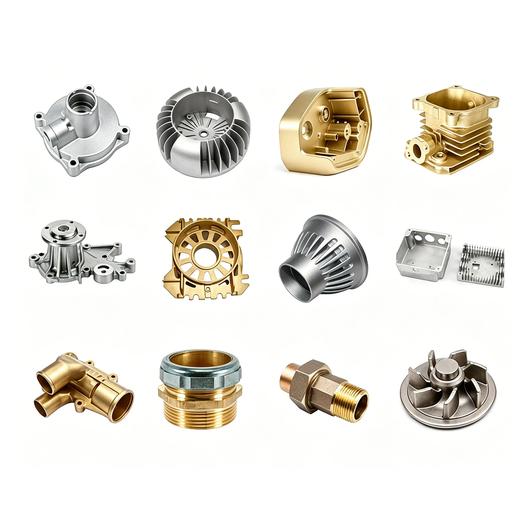
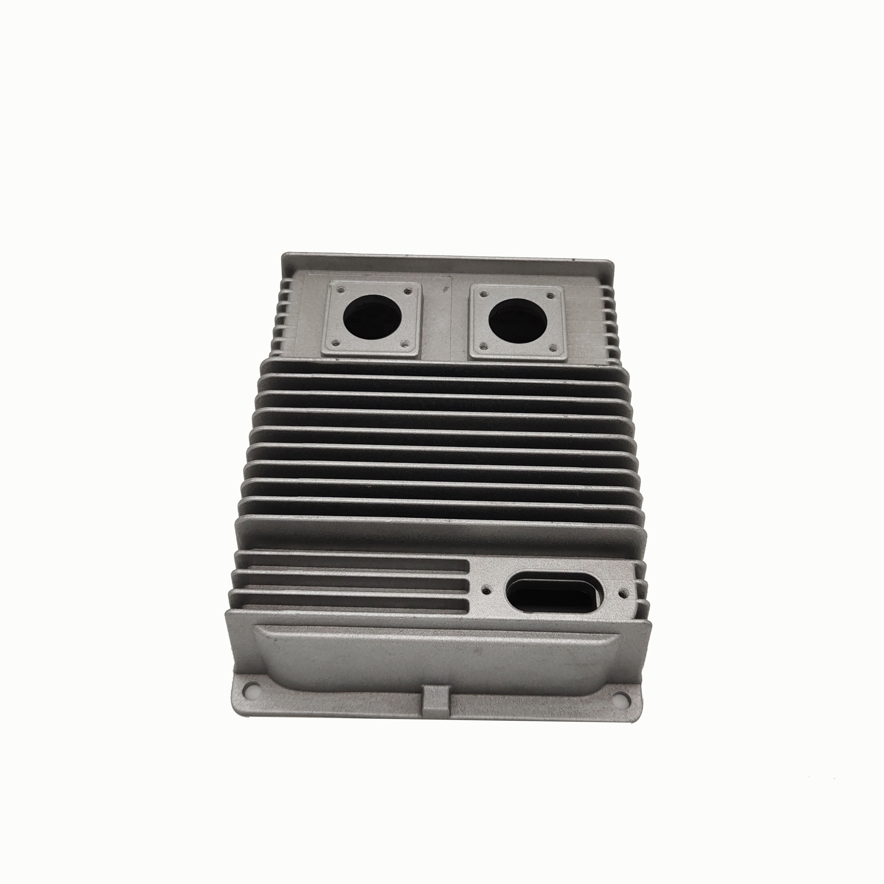
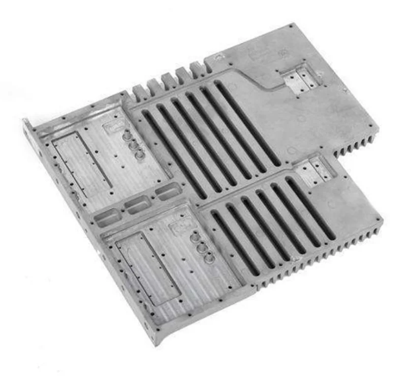
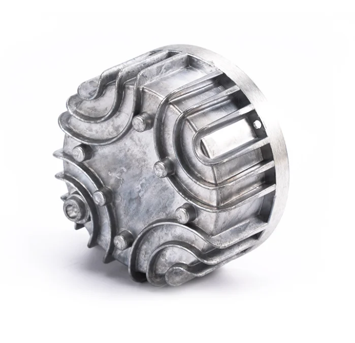
Precision aluminum machinery-part investment and lost wax casting is offered with polishing and CNC machining. Processing includes casting, deburring, drilling and threading. Steel casting projects should define their own material and component requirements separately from the primary aluminum enquiry.
Identify the machinery component and material
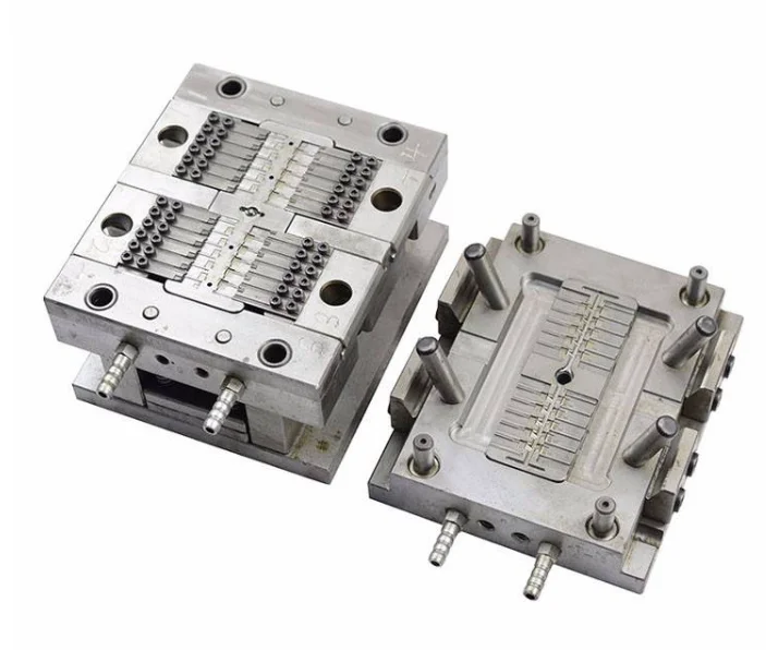
Provide the actual part drawing and selected alloy for the project. For components associated with casting or die-casting equipment, identify the required equipment-part role and mating dimensions before defining the manufacturing route. A steel enquiry needs its own grade and process confirmation so the proposal addresses the intended component.
Mark CNC, drilled and threaded dimensions
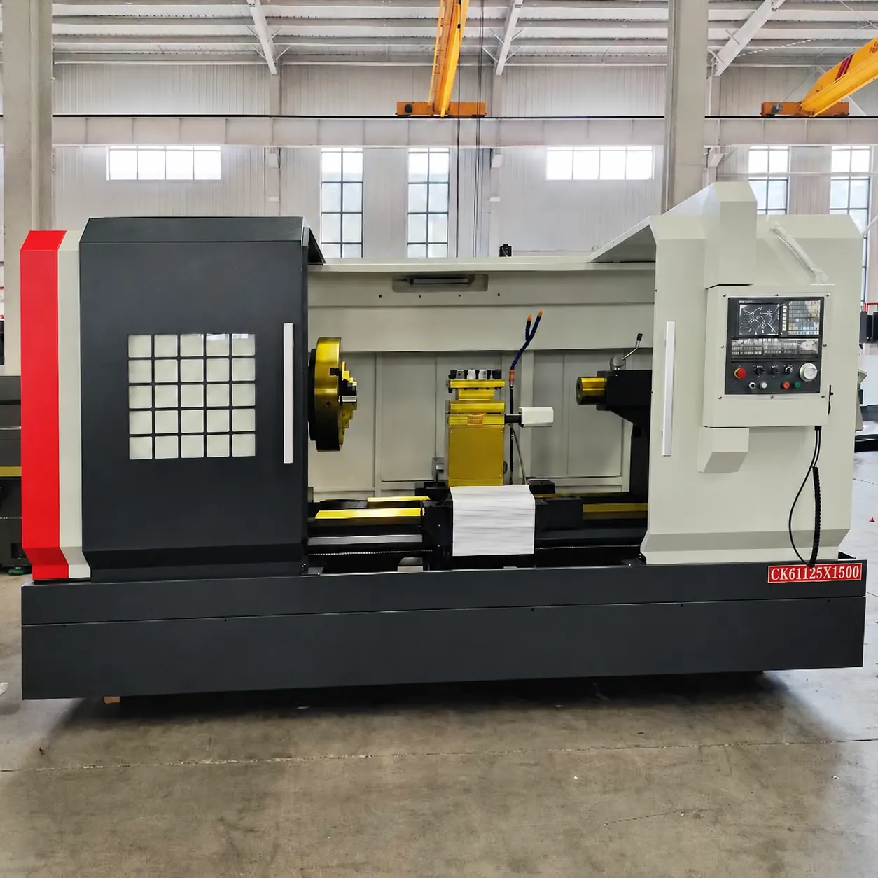
CNC machining center work is available alongside drilling and threading. Identify the dimensions, interfaces and thread requirements needing those operations, and agree their tolerance and measurement criteria. Keep the cast geometry and acceptance after machining clear on the drawing.
Define polished appearance and custom colour
Polishing and customized colour requirements can be discussed for the selected alloy. Mark the relevant surfaces and describe their required appearance or functional acceptance. Agree the surface requirements with the component's dimensions so the finished-part definition is consistent.
Use drawings and sample requirements to evaluate the part
Mark the CNC, drilled and threaded dimensions in the machinery part's 2D PDF/CAD drawing or 3D IGES/STEP model. Sample service can be discussed against the actual component drawing and acceptance criteria. Use one revision for material, CNC dimensions, drilled or threaded interfaces and surface requirements. Include the inspection acceptance needed for the machinery component so the proposed casting work can be evaluated for its intended duty.