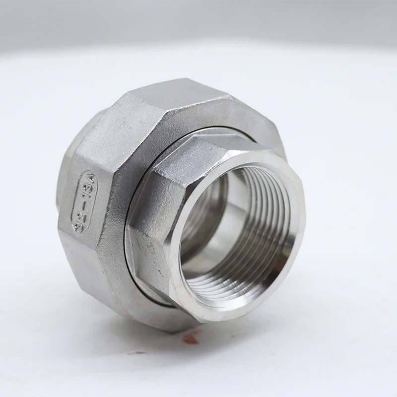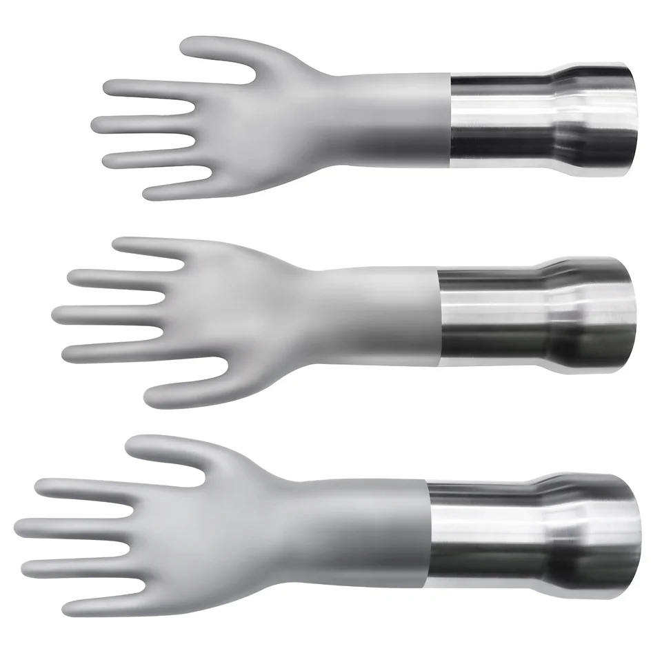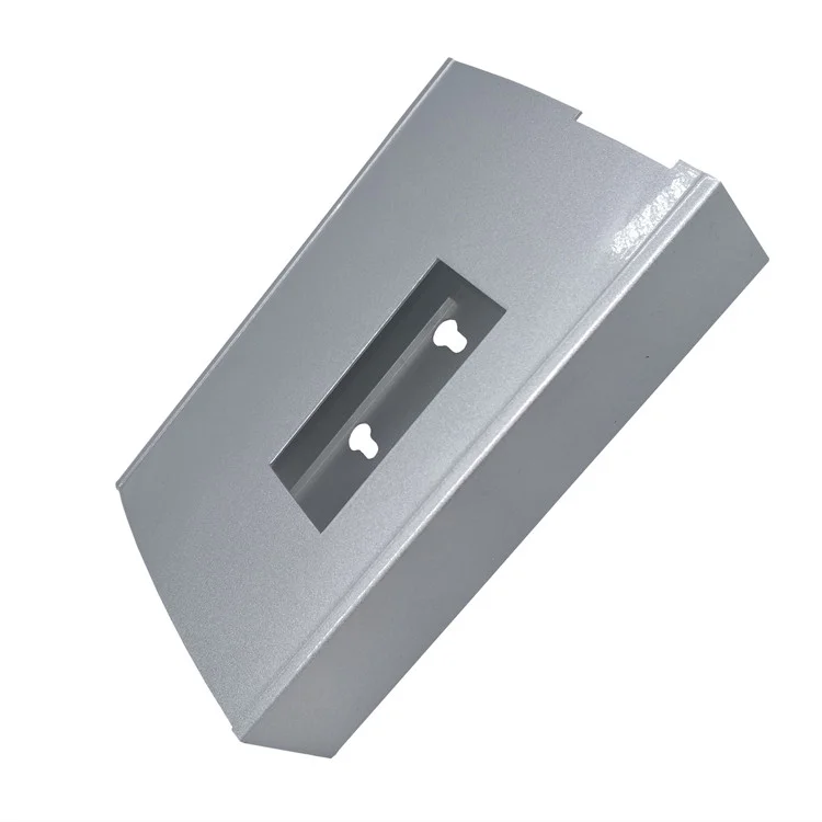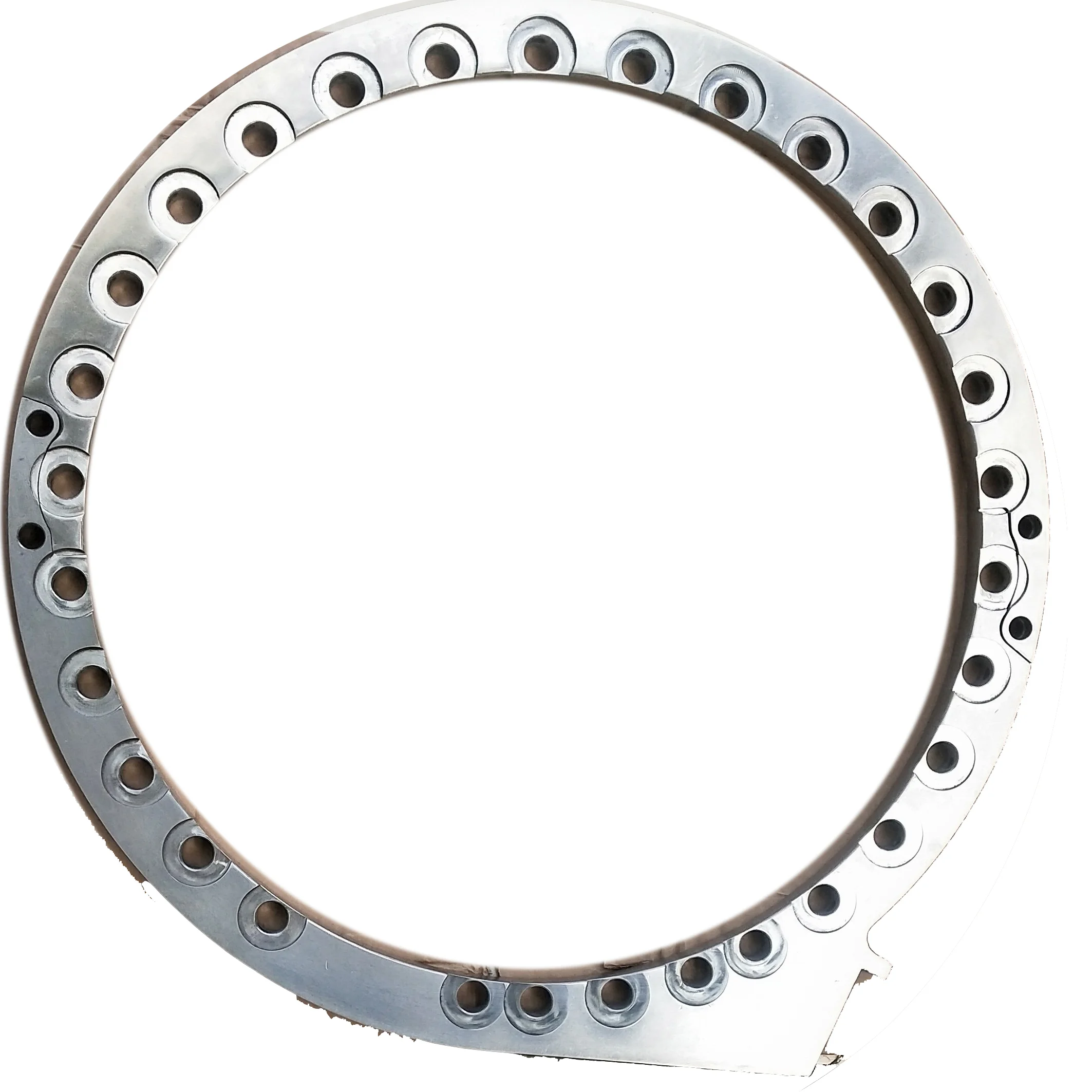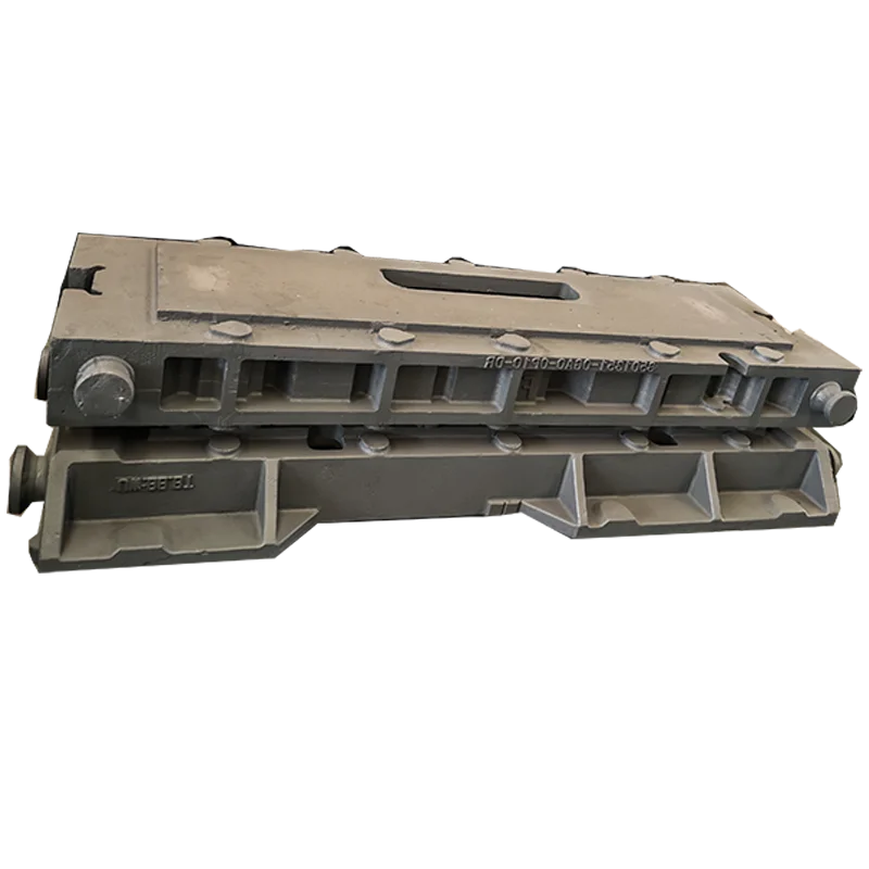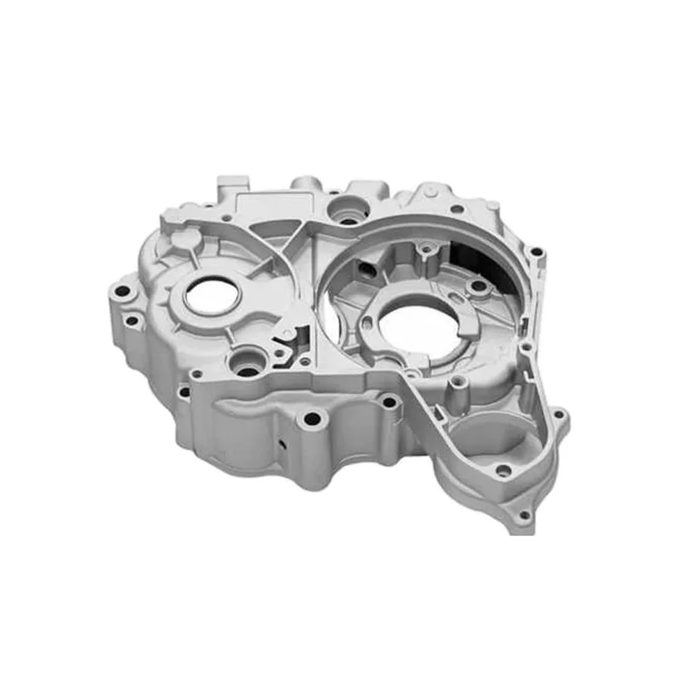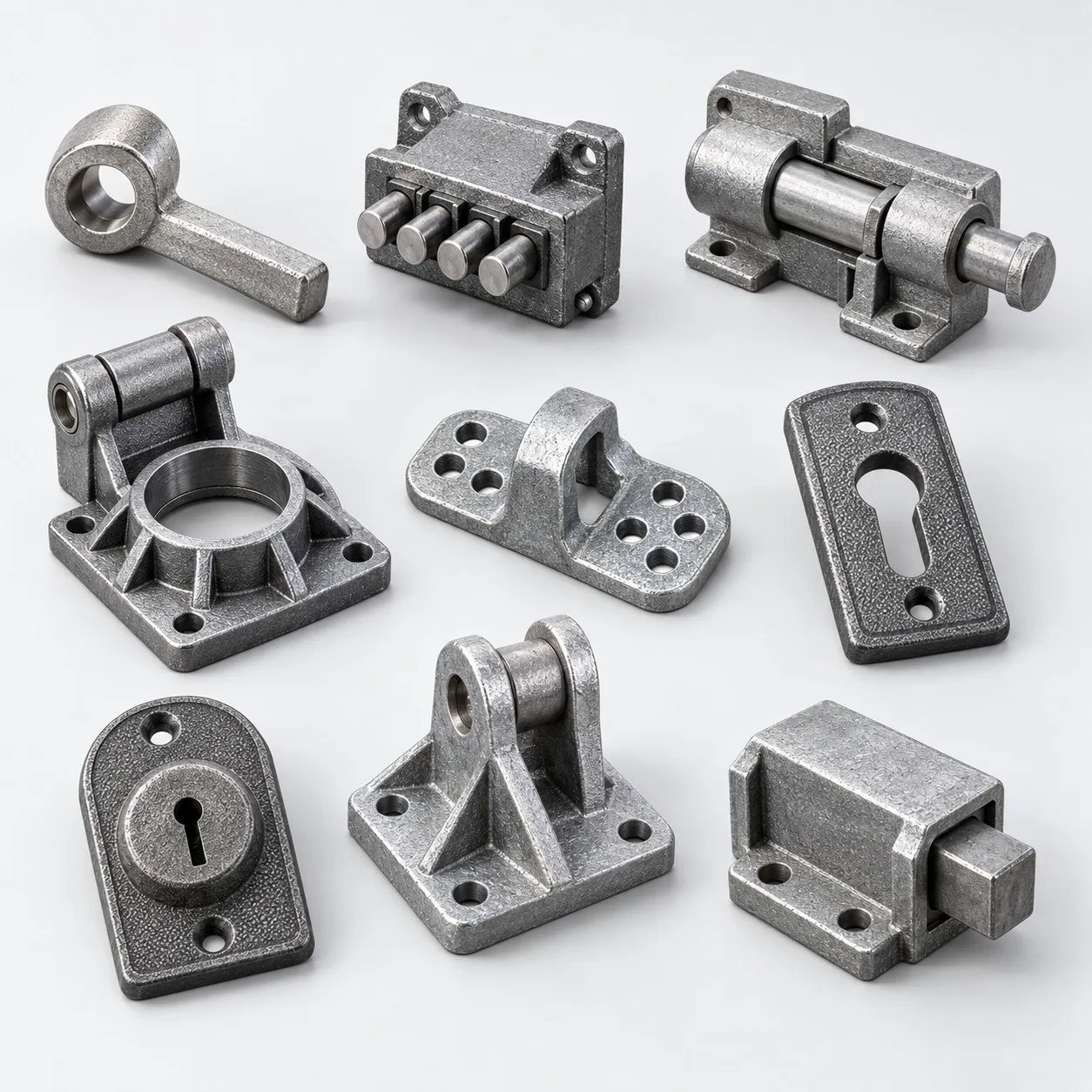
OEM/ODM Industrial Stainless/Cast-Iron/Aluminum Die-Casting Requests, Investment CT4–6/Sand CT10–12 References, Tooling and Prototyping
Let’s define your requirement
Send a product link, drawing or short brief. We’ll work through the details with you.
- Confirm the specificationGrade or model, size and intended use.
- Define your orderQuantity, finish or configuration, and samples.
- Agree the quotation scopeIncluded work, key checks and delivery needs.
-
Surface FinishPowder Coated , Shot Blasted
-
Casting MethodDie Casting
-
MaterialStainless Steel, Ductile Iron, Aluminum, Spectrometer AnalysisSurface TreatmentShot Blasting, Powder Coating, Hot Dip Galvanized, E-coating, Painting
-
Tolerance & Surface RoughnessCT4-CT6 (Investment), CT10-CT12 (Sand), Ra 1.6-3.2 (Smooth Finish)Tooling & Mold DesignIn-house Tooling Design, Mold Manufacturing, Prototyping Service
-
Service TypeOEM/ODM Custom Manufacturing / PrototypingDrawing FormatsSTEP, STP, IGES, DXF, DWG, PDF
-
CertificationISO 9001, IATF 16949 , AS 9100 , CE, RoHSQuality Control100% Inspection, CMM, Projector, Caliper, Salt Spray Test
-
Lead Time7-10 Days (Prototype), 15-25 Days (Mass Production)
Customized OEM and ODM industrial casting requests include stainless steel, cast/ductile iron and aluminum/aluminum-alloy directions. Die-casting requests require the actual material and route to be agreed. Tooling design, mold manufacture and prototyping support the selected component, with route-specific tolerance and finished acceptance requirements.
Material selection and three route references
Choose the supplied material specification and actual casting process for the industrial drawing. Investment references are CT4–6 and sand-casting references are CT10–12; define any die-casting limits separately. The smooth-finish reference is Ra 1.6–3.2, with its unit, locations and measurement conditions to confirm.
Tooling, prototype and drawing formats
Drawing formats include STEP, STP, IGES, DXF, DWG and PDF. Agree the tooling design, mold manufacturing and actual responsible in-house tooling scope for the chosen part. Define what the prototype must demonstrate and how it is accepted against the drawing and selected material/route.
Five finished-surface choices
Shot blasting, powder coating, hot-dip galvanizing, e-coating and painting are finishing directions. Select the treatment and covered areas appropriate to the actual component. Agree its final surface condition together with the route-specific dimensions and roughness requirements.
Full inspection and allocated methods
The inspection direction is 100%, with actual characteristics and records to agree. Method directions include spectrometer analysis, CMM, projector, caliper and salt-spray testing. Allocate the relevant methods, coverage and acceptance criteria to the selected material, dimensions and surface condition.
ISO/IATF/AS and CE/RoHS for tooling and cast-part scope
For the chosen material and casting route, identify the applicable ISO9001, IATF16949 and AS9100 quality-system documents and responsible organization/site. Establish the actual object and document basis for any CE or RoHS conformity requirement. Apply the relevant scope to tooling/prototype acceptance and final cast-part requirements; agree quantity and customized OEM/ODM responsibilities with the accepted drawing, finish and inspection plan.