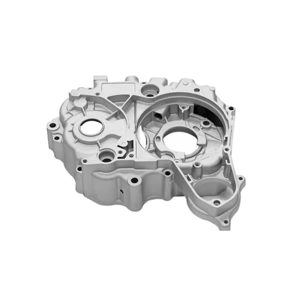
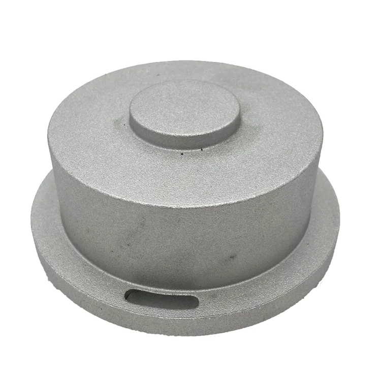
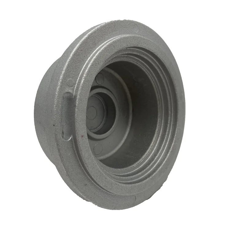
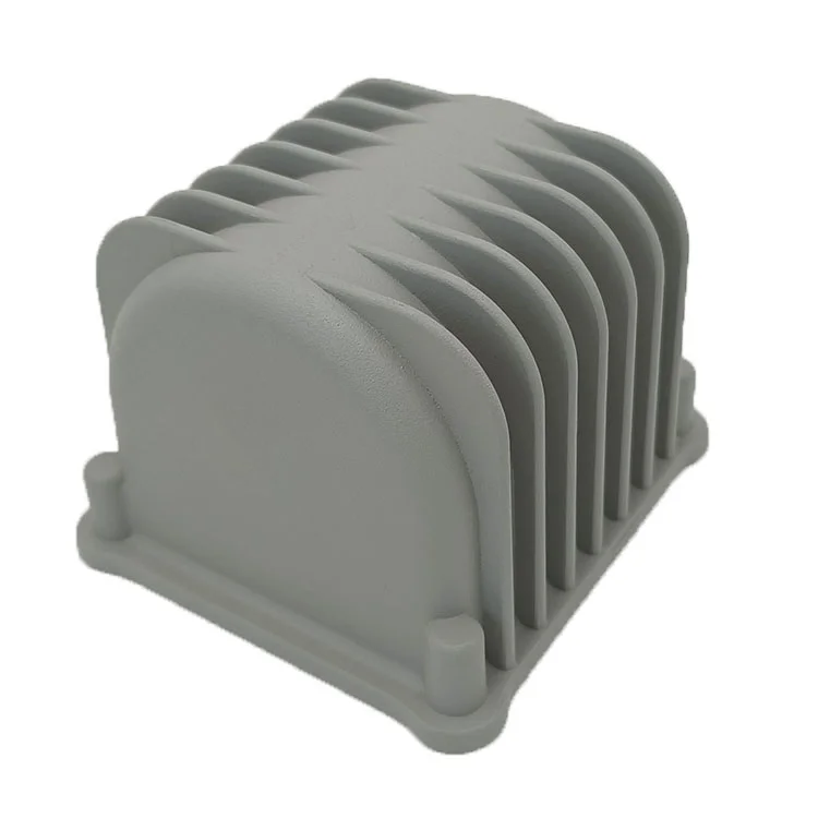
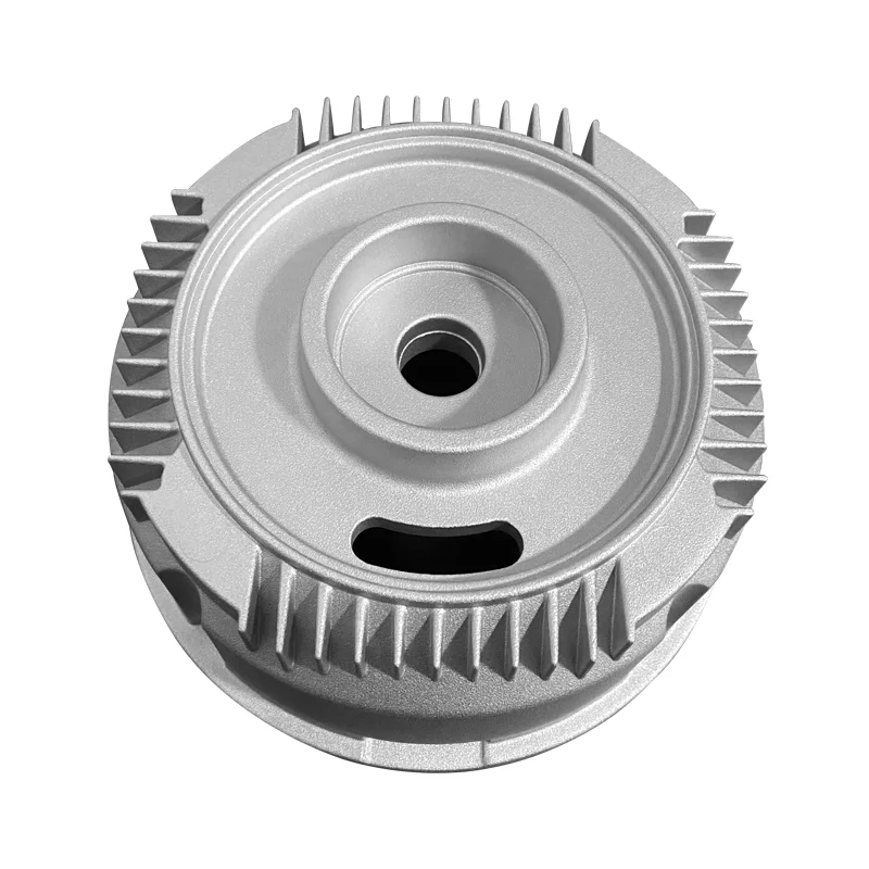
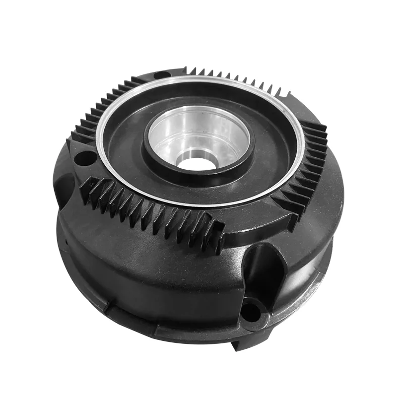
OEM Aluminum Enclosure Motor Cover and Gearbox Housing Casting with CNC and Mold Development
Let’s define your requirement
Send a product link, drawing or short brief. We’ll work through the details with you.
- Confirm the specificationGrade or model, size and intended use.
- Define your orderQuantity, finish or configuration, and samples.
- Agree the quotation scopeIncluded work, key checks and delivery needs.
-
Component FormHousing / EnclosureSurface FinishPowder Coated , Sandblasted
-
Alloy GradeA380 , ADC12
-
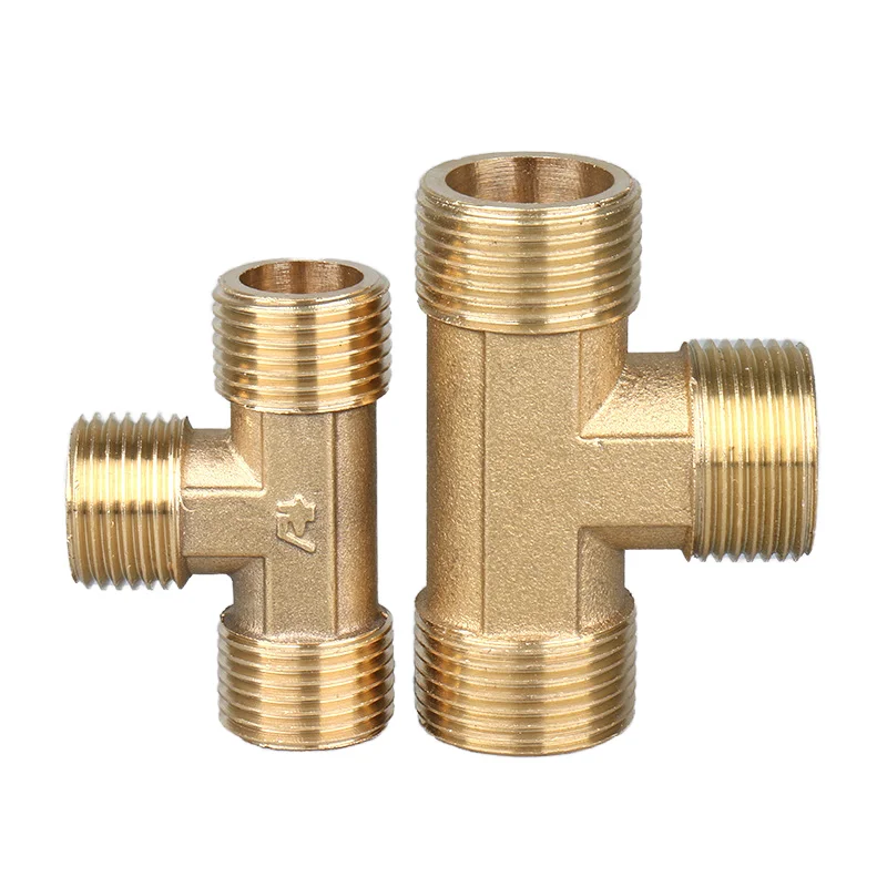
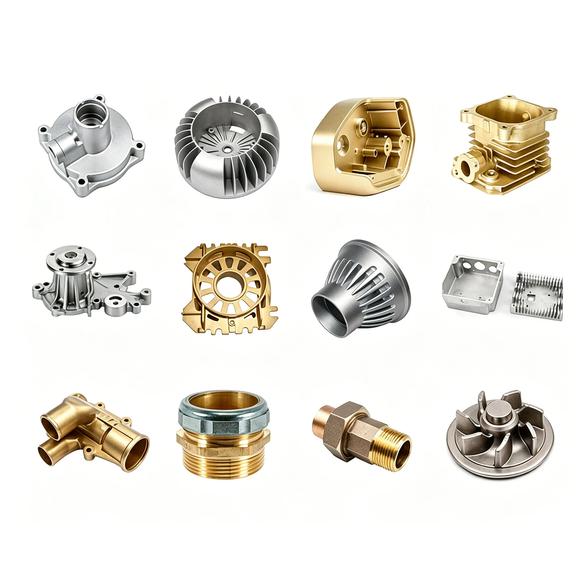
MaterialADC12 / A380 / Zamak 3 / Zamak 5 / Brass / Copper Customized
-
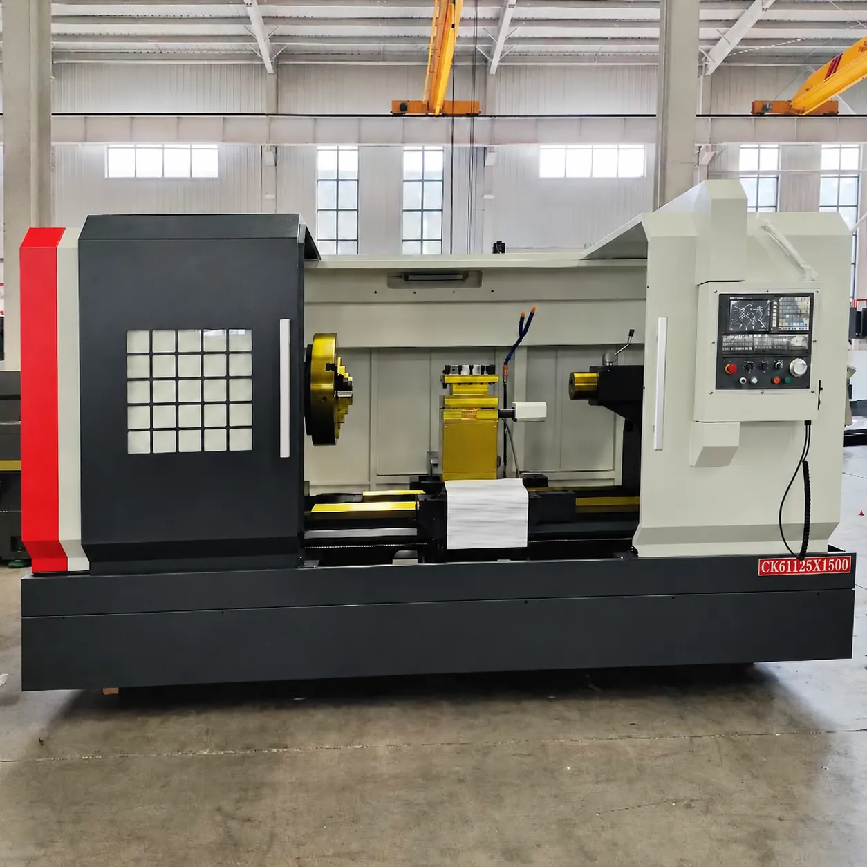
ProcessPrecision Casting / CNC Machining / Surface FinishingSurface TreatmentPowder Coating / Anodizing / Sandblasting / Plating
-
Tolerance±0.01- 0.05mmLead Time20-35 Day
-
Drawing FormatPDF / STEP / IGES / DWG / 3D FilesMOQ10pcs / Flexible (depends on structure)
-
Custom SupportTechnical SupportMold DevelopmentIn-House Mold Design and Manufacturing
-
Quality ControlCMM Inspection / Material Verification / Batch Sampling Inspection
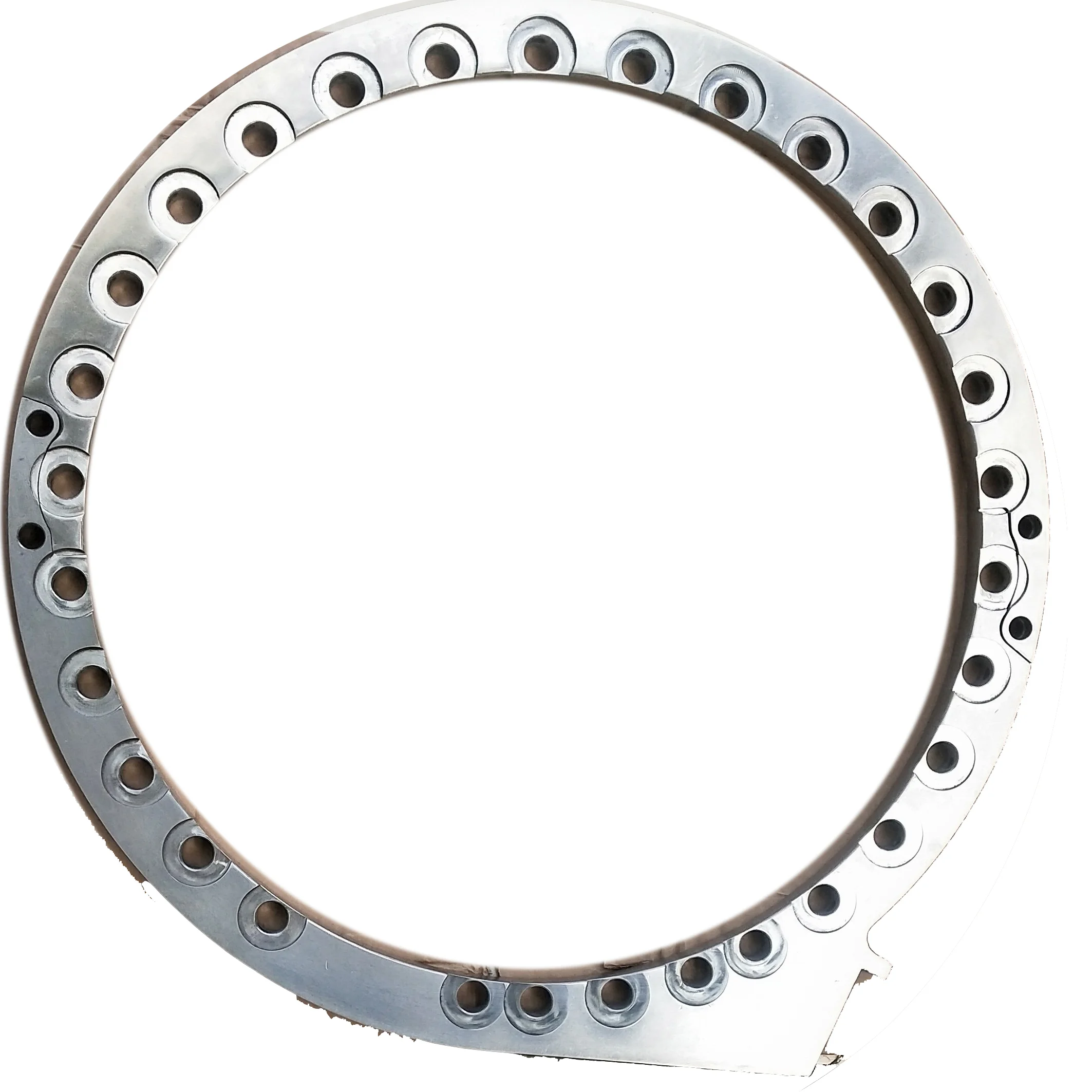
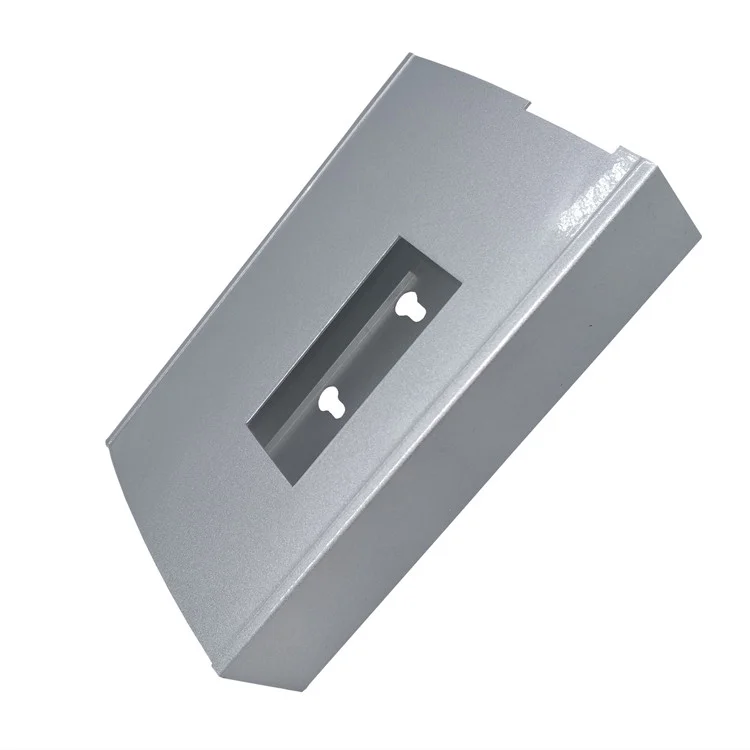
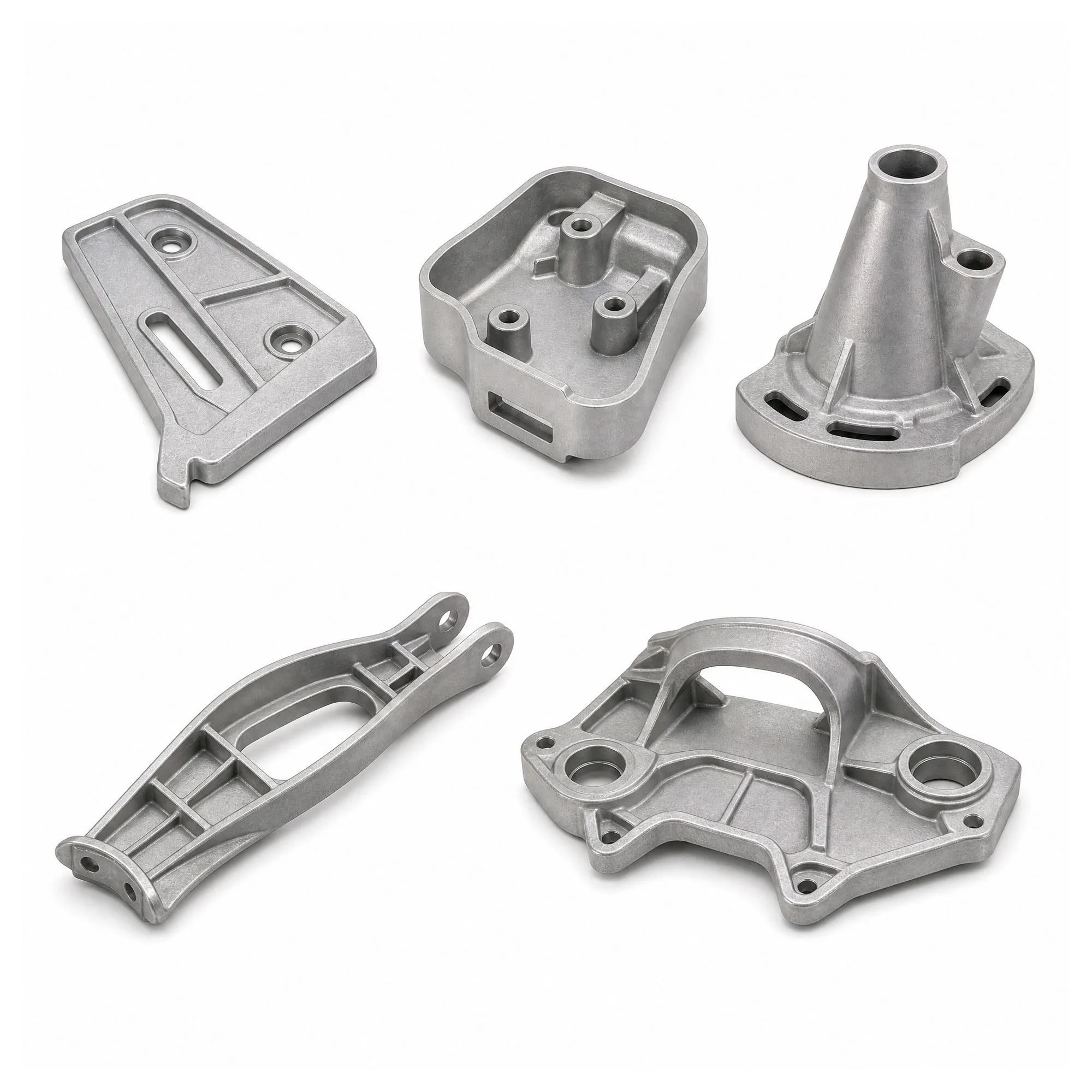
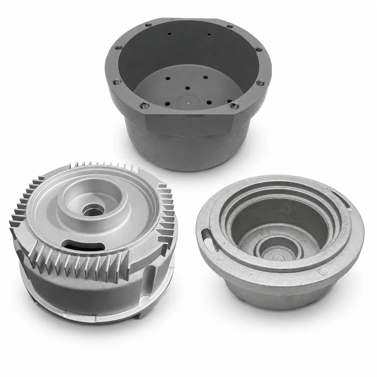
Custom enclosure, motor-cover and gearbox-housing requests combine precision casting, CNC machining and surface finishing. Technical support and in-house mold design and manufacturing are offered, allowing the component and its mold requirements to be discussed together.
Define the housing and mold as related requests
Identify the enclosure, cover or housing geometry and the interfaces that locate it in the intended assembly. Agree the mold-development scope for that component, including the shape and finished requirements it must support. This connects the tooling discussion to the actual part being requested.
Select material and treatment for the component
Material choices include ADC12, A380, Zamak 3, Zamak 5, brass and copper, with the actual route agreed for the selected metal. Powder coating, anodizing, sandblasting and plating are finish directions. Identify the treated areas and the final condition required at mating surfaces.
Assign dimensional acceptance to the inspection plan
The tolerance direction is ±0.01–0.05 mm, with the applicable limits to be assigned to the relevant dimensions. Quality control includes CMM inspection, material verification and batch sampling inspection. Define which characteristics are checked and how the selected material and component geometry will be accepted.
- Dimensional definition
- Show the cast and machined interfaces that establish fit.
- Material definition
- Identify the chosen metal and the verification required for the order.
Prepare geometry and a structure-based quantity
PDF, STEP, IGES, DWG and 3D files can be used for the component definition. The minimum-order direction is 10 pieces, flexible depending on structure, so agree the actual quantity with the housing and mold scope. Include the selected material, treatment and acceptance requirements with the files to give the custom order a consistent description.