High-Precision Aluminum Die Casting for Drawing-Based Engine and Transmission Parts, Molds and Prototypes
Let’s define your requirement
Send a product link, drawing or short brief. We’ll work through the details with you.
- Confirm the specificationGrade or model, size and intended use.
- Define your orderQuantity, finish or configuration, and samples.
- Agree the quotation scopeIncluded work, key checks and delivery needs.
-
Component FormGear / Transmission PartSurface FinishAnodized , Powder Coated
-
SizeOEM/ODM Supported (Size, Material, Surface Finish)Surface TreatmentMill Finish, Anodizing, Powder Coating, Electropla
-
MaterialsZinc, Aluminum, Magnesium, Stainless Steel, etc.Tolerance Standard±0.05mm, Custom Tolerance Available
-
Die Casting ProcessHigh-Pressure Die Casting, Precision Die CastingApplication FieldAutomotive, Electronics, Industrial Machinery, Medical Devices
-
Quality CertificationISO 9001, IATF 16949, RoHS CompliantLead Time7-15 Days for Samples, 20-30 Days for Mass Production
-
Drawing Format3D.STP. STEP . IGS . PRT . X_TPackageCustomers Specific Requirement
-
ProcessDie casting moldQuality Control100% Inspection, CMM, Projector, Caliper, Salt Spray Test
-
Service TypeOEM/ODM Custom Manufacturing / Prototyping
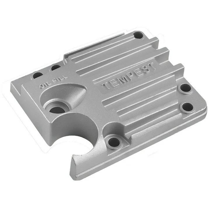
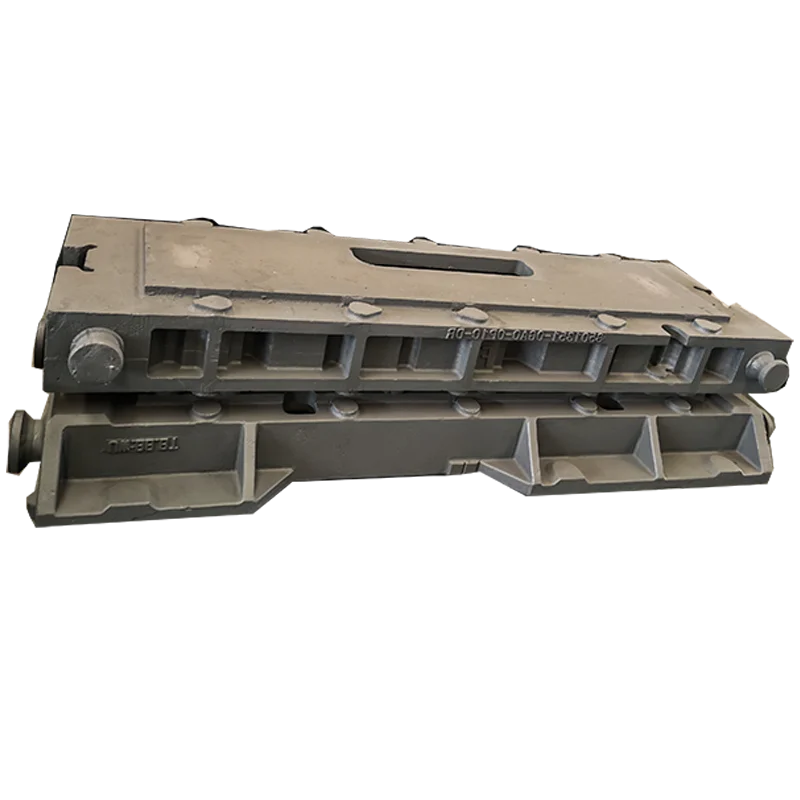
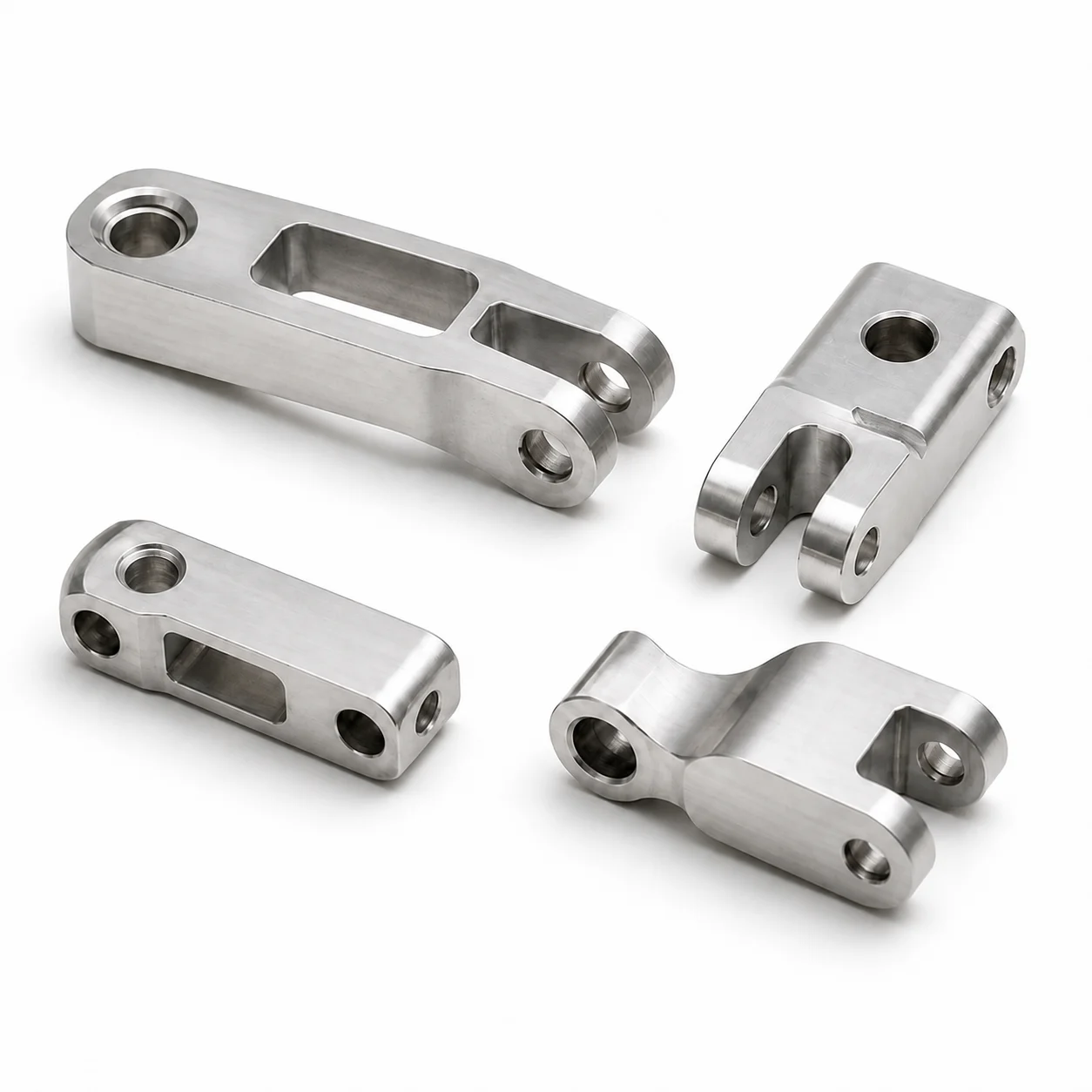
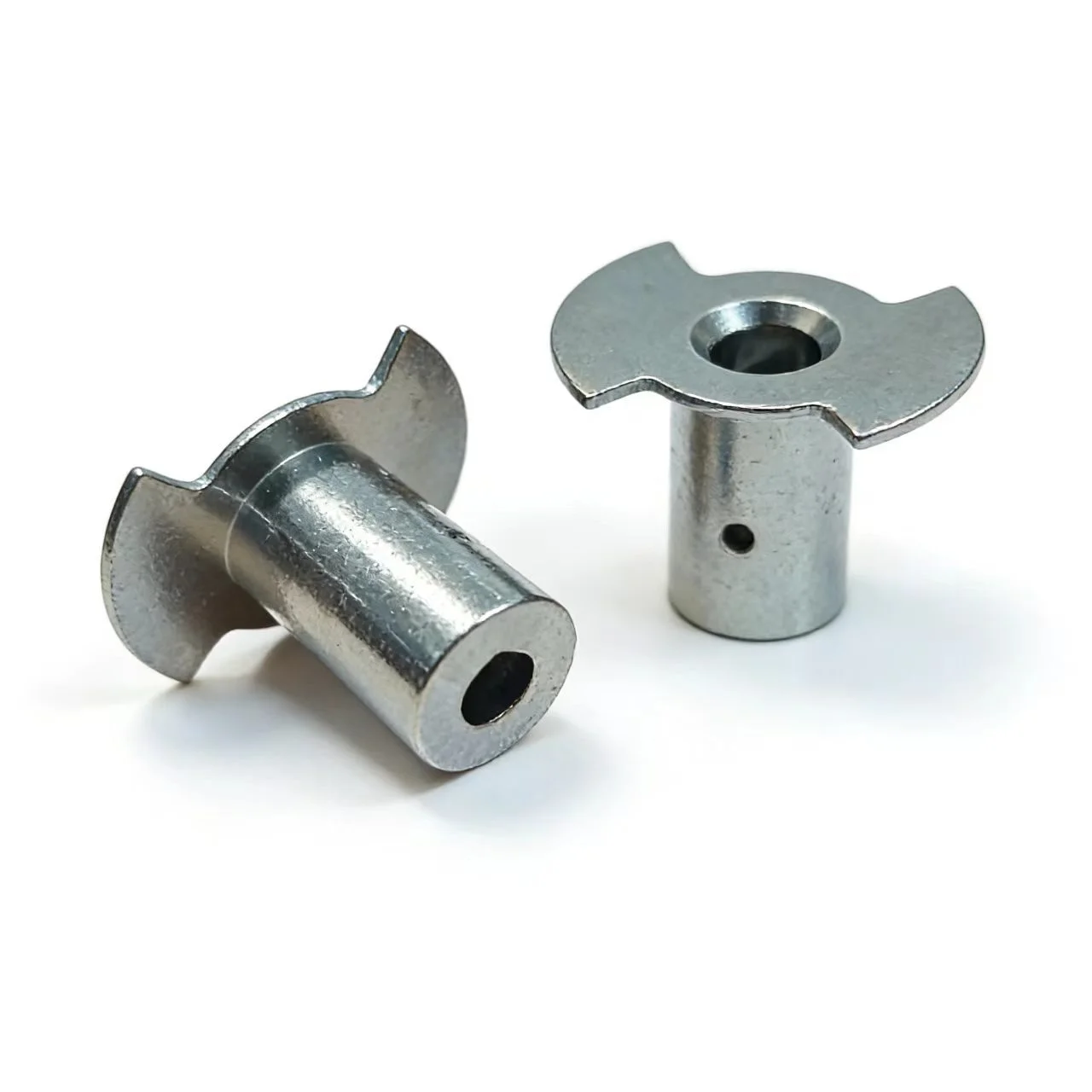
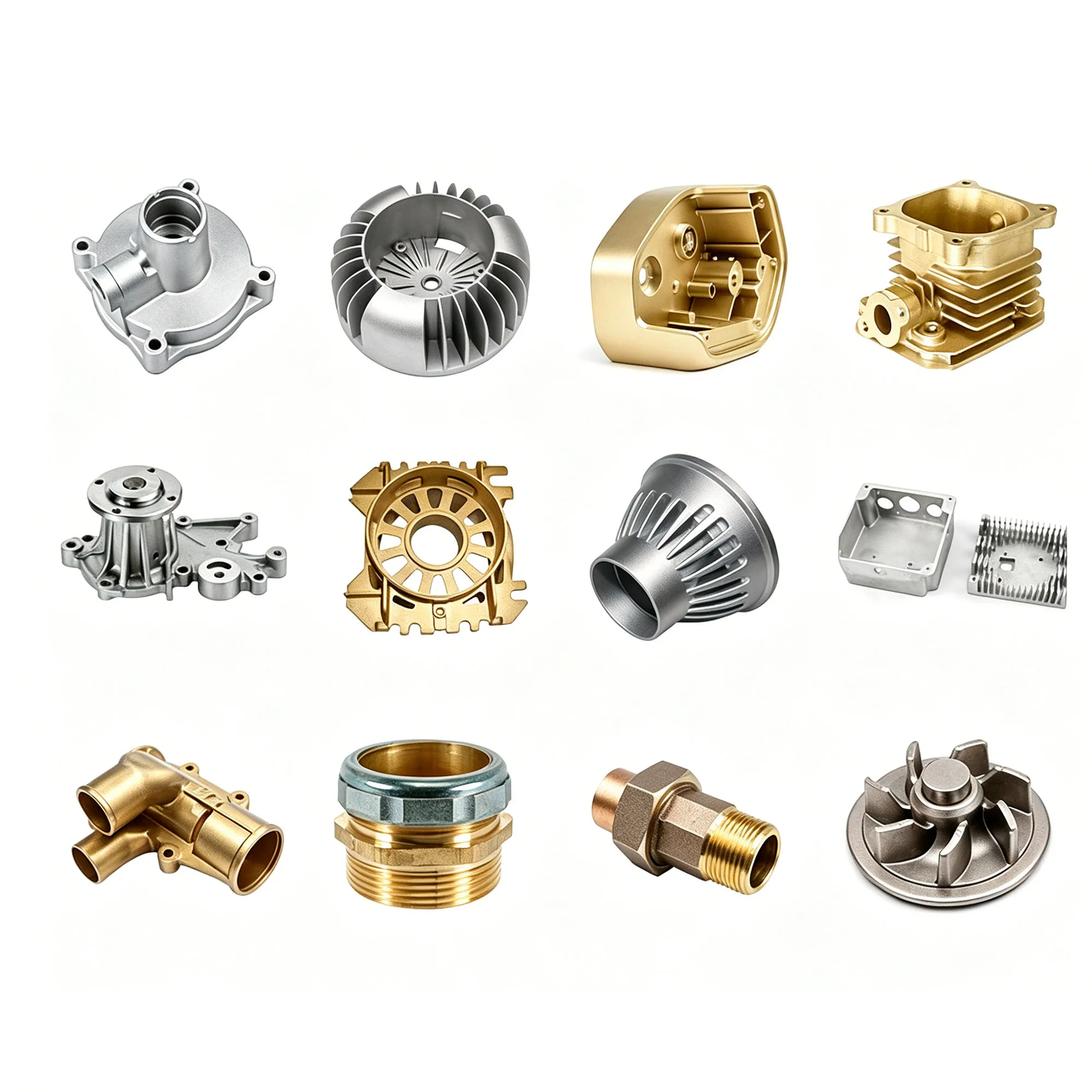
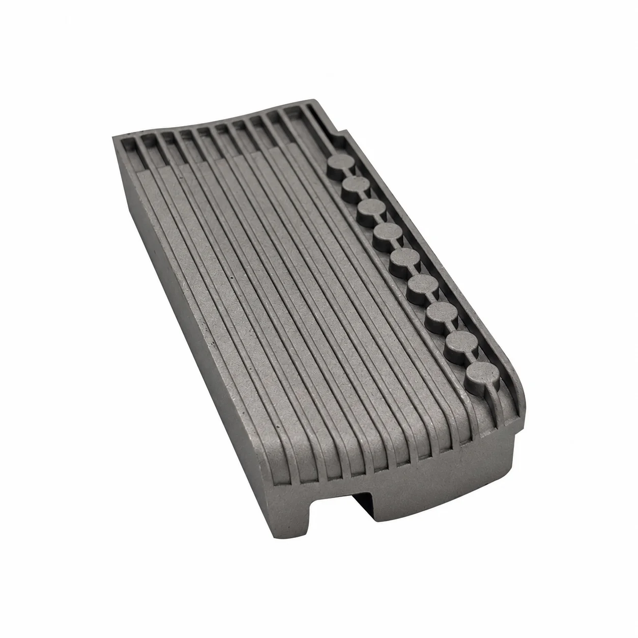
Drawing-based aluminum die casting is offered for engine and transmission metal parts, with high-pressure and precision die-casting directions. OEM/ODM work includes casting molds and prototyping, plus customization of size, material and surface finish. The component drawing can therefore define both the part and the manufacturing scope to be reviewed.
Engine and transmission part definition
Aluminum is the primary material direction for this part inquiry, with zinc, magnesium and stainless steel among the broader material choices. Choose the actual alloy and agree the appropriate route for the component. Automotive, electronics, industrial machinery and medical-device work are application directions, each needing the intended part function and acceptance defined for its use.
Tolerance and the finished surface
The tolerance reference is ±0.05 mm, with custom tolerance available. Mill finish, anodizing and powder coating are selectable surface directions for the design. Connect the required tolerance to the drawing features and decide which surfaces receive the chosen finish, so the geometry and delivered condition are reviewed as one component requirement.
Prototype, mold and measurement review
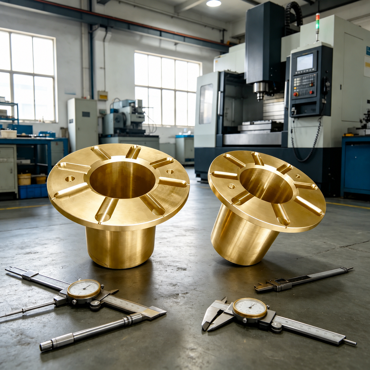
OEM/ODM custom manufacturing and prototyping support the drawing-based request, with STP/STEP, IGS, PRT and X_T among the 3D formats. Quality control includes 100% inspection and CMM, projector, caliper and salt-spray testing capabilities. Agree the dimensional measurements and any relevant surface-test conditions for the part before defining its acceptance.
- Cast component
- Identify the engine or transmission part, selected alloy and mold requirement.
- Dimensional review
- Assign the ±0.05 mm reference or custom tolerance to the actual drawing features.
- Delivered condition
- Choose the finish and connect inspection or coating-test criteria to that selection.