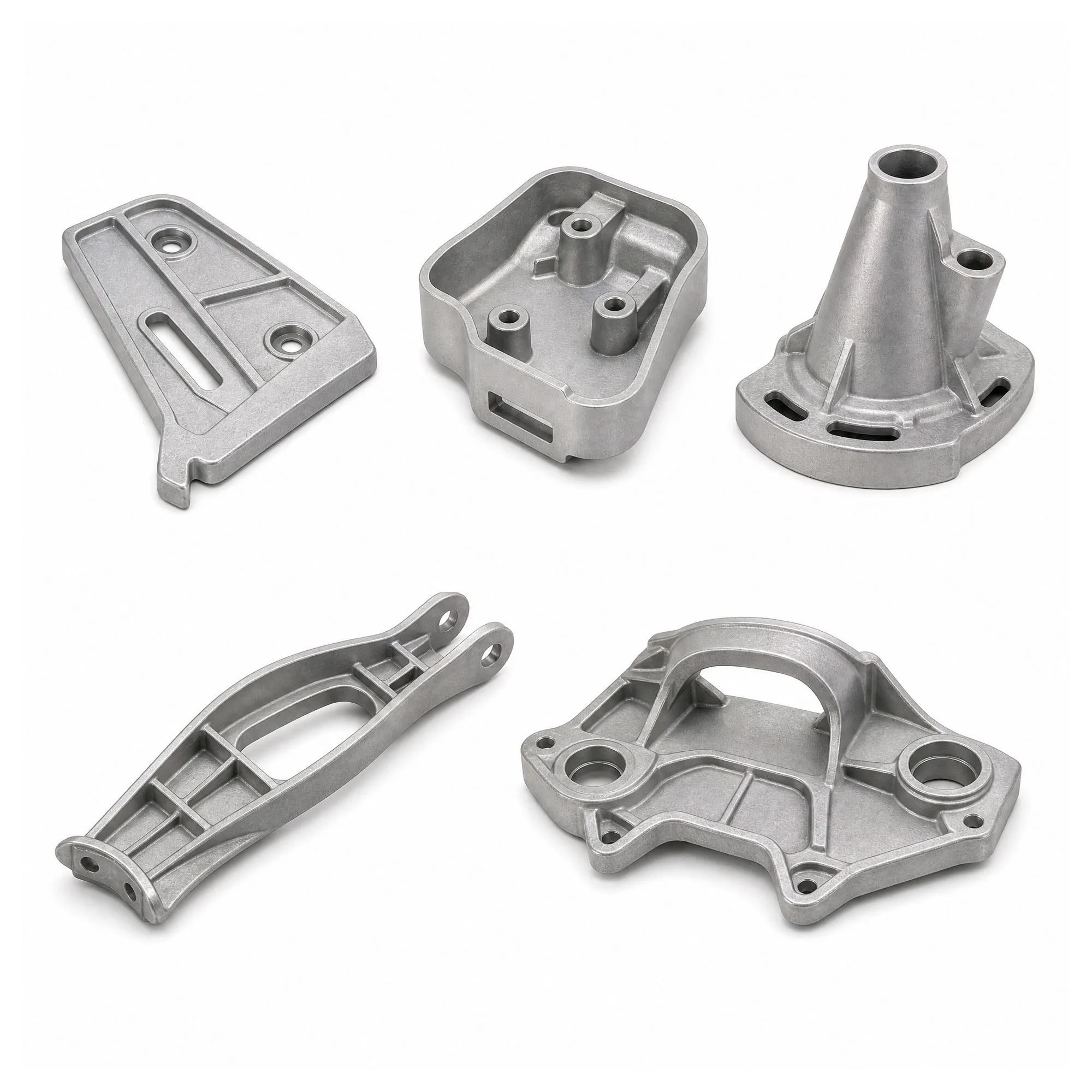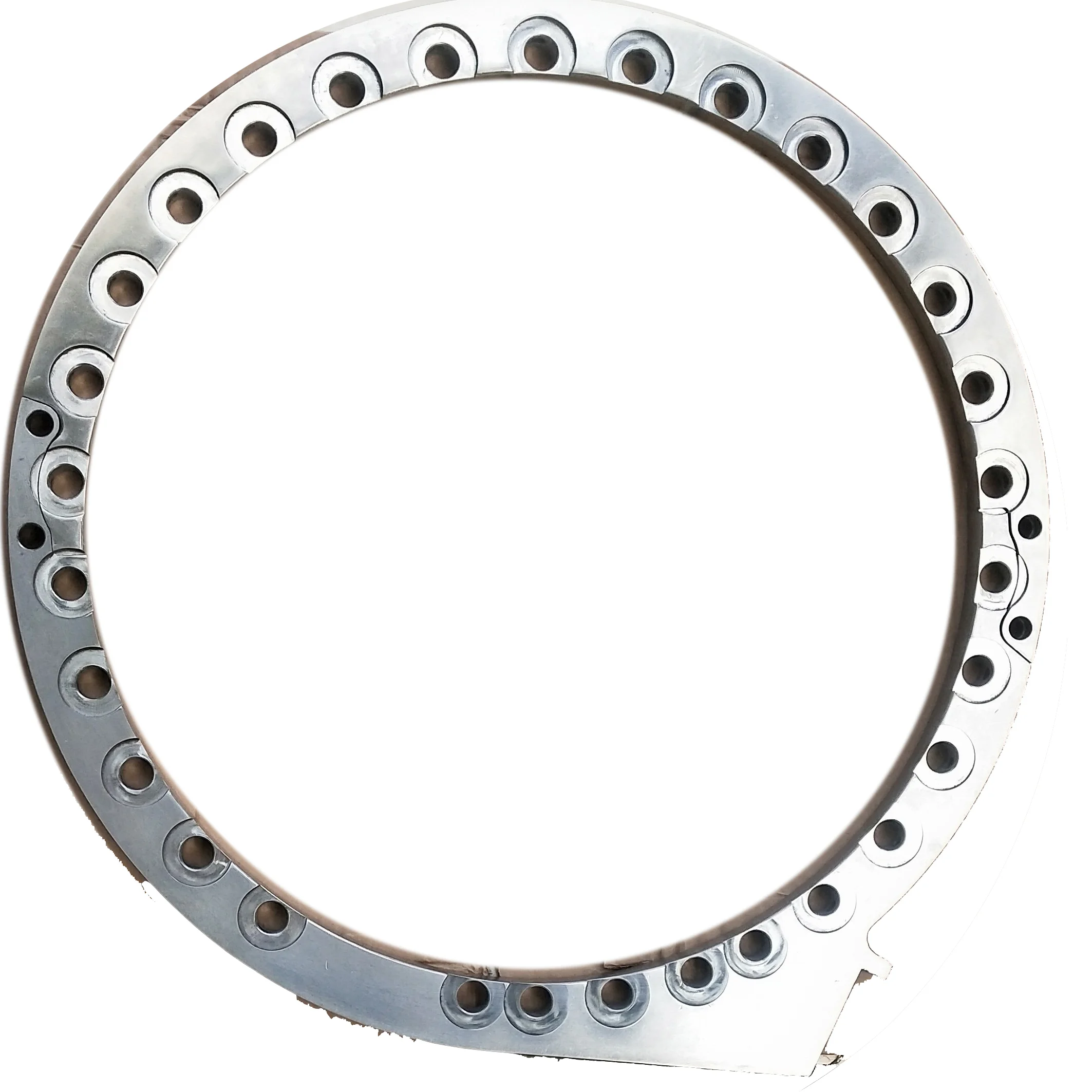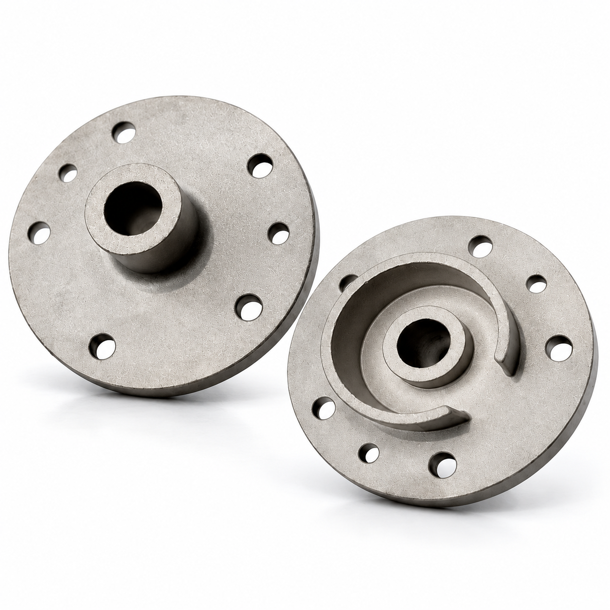
Custom Stainless Steel Flange Hardware, Lost-Wax Investment Casting and CNC Machining
Let’s define your requirement
Send a product link, drawing or short brief. We’ll work through the details with you.
- Confirm the specificationGrade or model, size and intended use.
- Define your orderQuantity, finish or configuration, and samples.
- Agree the quotation scopeIncluded work, key checks and delivery needs.
-
Component FormFlange
-
SizeCustmer's Drawings
-
Surface TreatmentPerfect AppearanceMaterialsstainless steel
-
NameCustom Flange Hardware Combine ProductsMaterialStainless Steel/Carbon Steel
-
Surface treatmentNo cape burr sand holeKeywordStainless steel precision casting
-
Quality Control100% InspectionTolerance0.2mm
-
Machining ProcessLost Wax+CNC MechiningLead Time15-35 Days
-
SurfacePerfect AppearanceDimensionsCustmer's Drawings
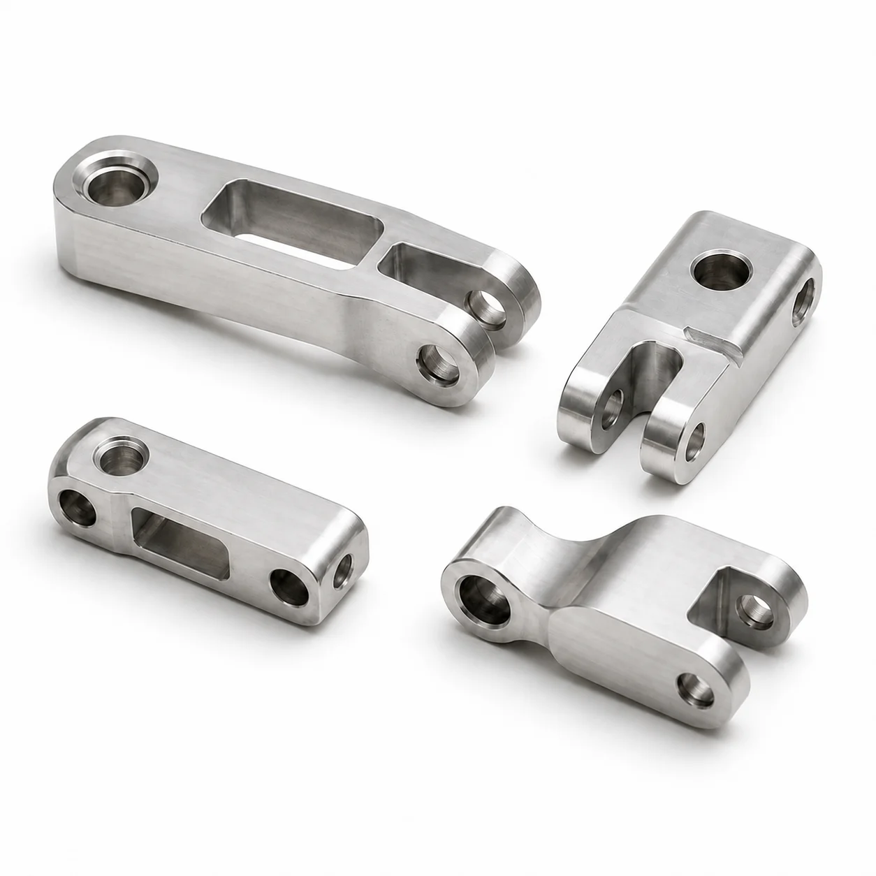
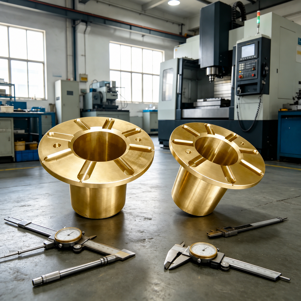
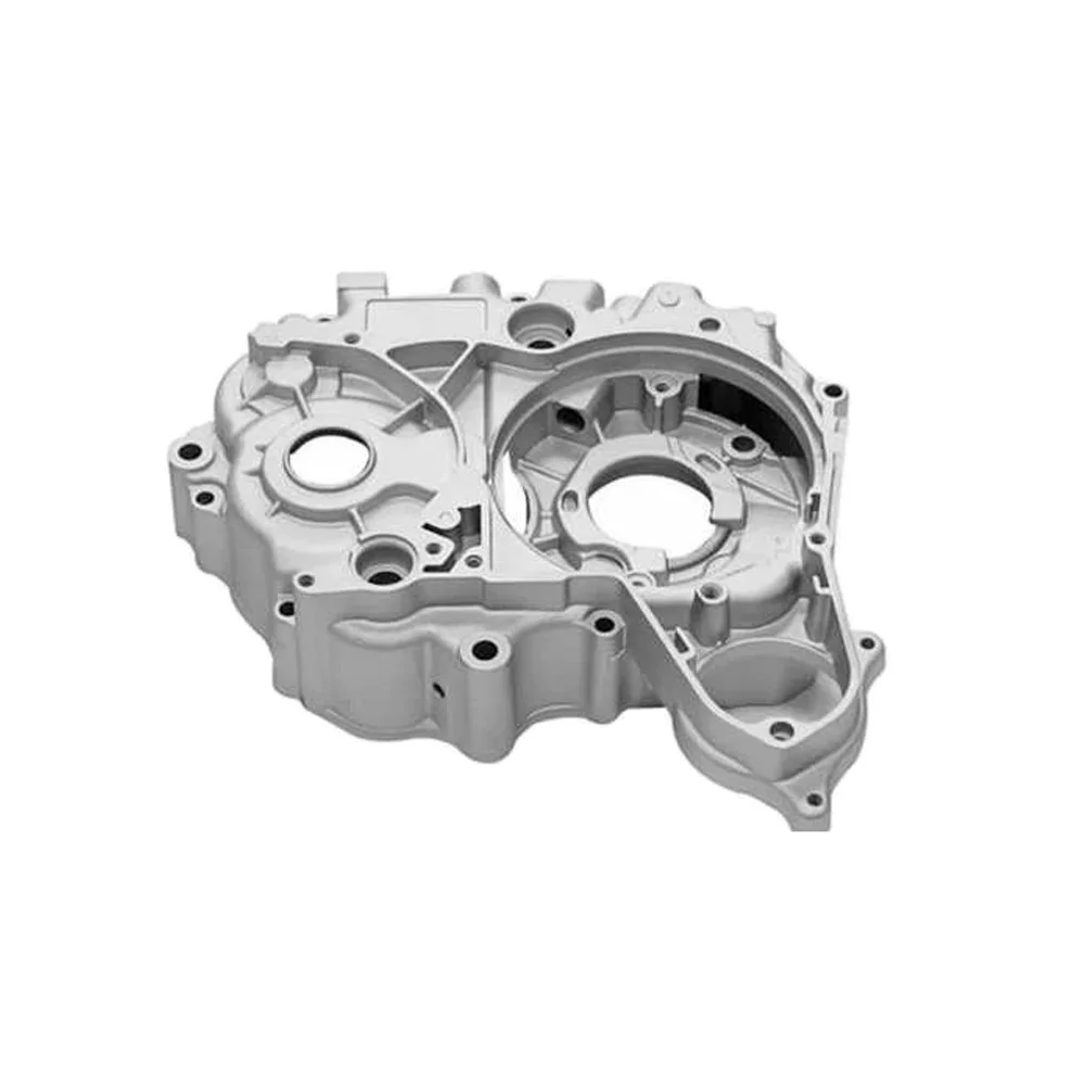
Custom flange hardware components combine lost-wax investment casting with CNC machining. Stainless steel is the primary material direction, with carbon-steel alternatives to select for the actual part. Sizes follow customer drawings, and the tolerance reference is 0.2 mm, to be related to the chosen features.
Flange geometry for the required connection
Identify the flange-hardware component and the way its interfaces meet the adjoining hardware. The drawing should define the required dimensions and the material grade for that connection. Keeping the geometry and intended function together makes the inquiry specific to a component rather than a general request for stainless-steel casting.
Cast form, CNC work and 0.2 mm
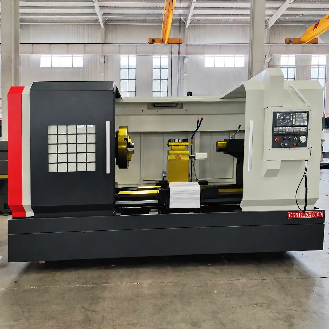
Lost-wax casting and CNC machining provide the process direction. Distinguish the cast form from the interfaces requiring machining and agree how the 0.2 mm reference applies to their acceptance. The tolerance sign and feature scope should be defined in the project requirements, so the finished geometry is assessed against an agreed dimensional basis.
Surface appearance and inspection criteria
Surface objectives address appearance, burr control and sand-hole acceptance. Define observable criteria for those requirements and identify the surfaces to which they apply. The component receives 100% inspection, with material, dimensional and appearance checks agreed for the chosen hardware. Connect that acceptance to the actual connection and any operating requirements the application demands. This provides a practical basis for reviewing the custom flange part without replacing its specific drawing requirements with a broad appearance description.