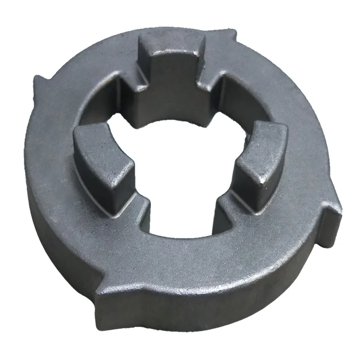
Precoated Sand Shell Moulding Railway Parts | Lost-Wax Casting and CNC Route Inquiry
Let’s define your requirement
Send a product link, drawing or short brief. We’ll work through the details with you.
- Confirm the specificationGrade or model, size and intended use.
- Define your orderQuantity, finish or configuration, and samples.
- Agree the quotation scopeIncluded work, key checks and delivery needs.
-
Surface FinishShot Blasted , Polished
-
SizeMax Linear Size: 1000 mm; Max Diameter Size: 600 m
-
Surface TreatmentE-coating/Zinc Plating/Mirror Polishing/Sand Blast, Shot blasting+AssemblingMaterialsCarbon Steel/Alloy Steel/Stainless Steel/Cast Iron
-
NamePrecoated Sand Shell Moulding Casting Parts FactoryKeywordsmodel casting
-
AppplicationRailwayProcessLost wax investment casting+CNC machined
-
Heat TreatmentQuench and temper by 2 set mesh belt furnacesMachining Facility60+ Machining centers,70+ CNC machines
-
InspectionMT/UT/RT/100% visual+100%gage/CMMStandardASTM. AISI. DIN. BS. JIS. NF. AS.
-
CertificationIATF16949/ISO14001
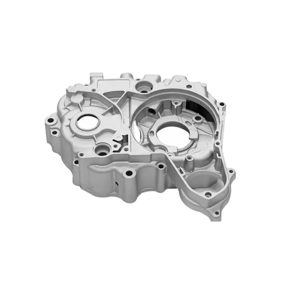
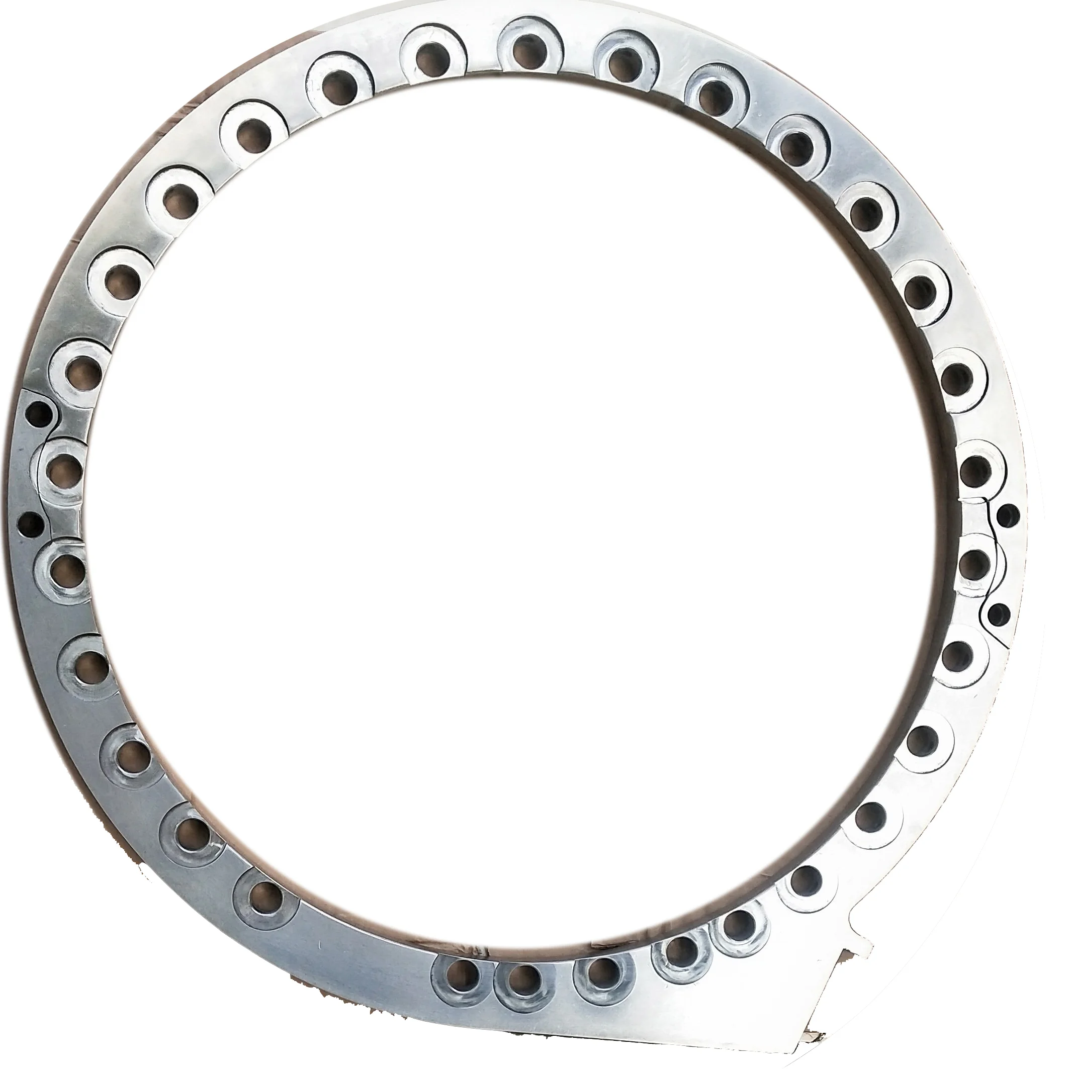
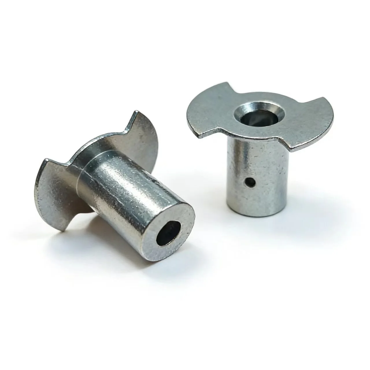
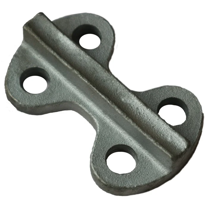
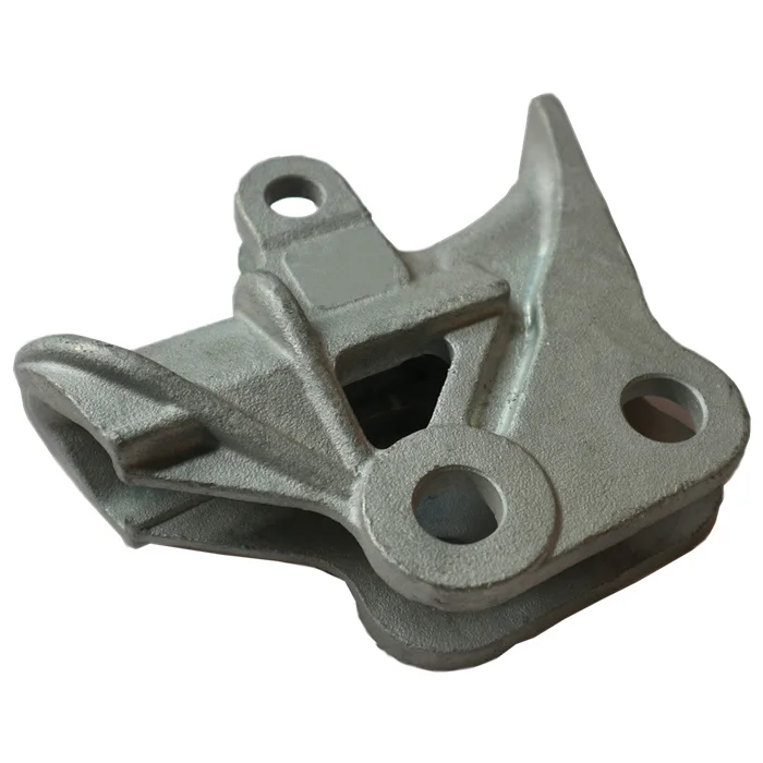
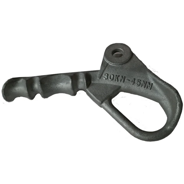
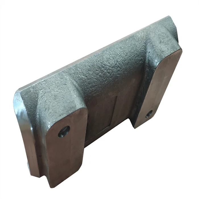
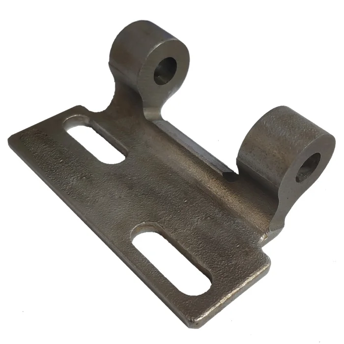
Railway casting inquiries cover carbon steel, alloy steel, stainless steel and cast iron, with CNC machining and secondary-process support. Precoated-sand shell moulding and lost-wax investment casting are manufacturing directions to confirm for the chosen part. Select the component and material before agreeing its casting route.
Railway geometry and the selected casting route
Define the actual railway component, its drawing and the required grade. The maximum linear-size reference is 1000 mm; the applicable diameter limit and unit need confirmation for the proposed geometry. Agree whether precoated-sand shell moulding or lost-wax investment casting applies, and identify the features requiring CNC machining within that route.
Heat treatment and machining capability
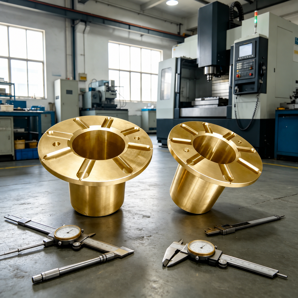
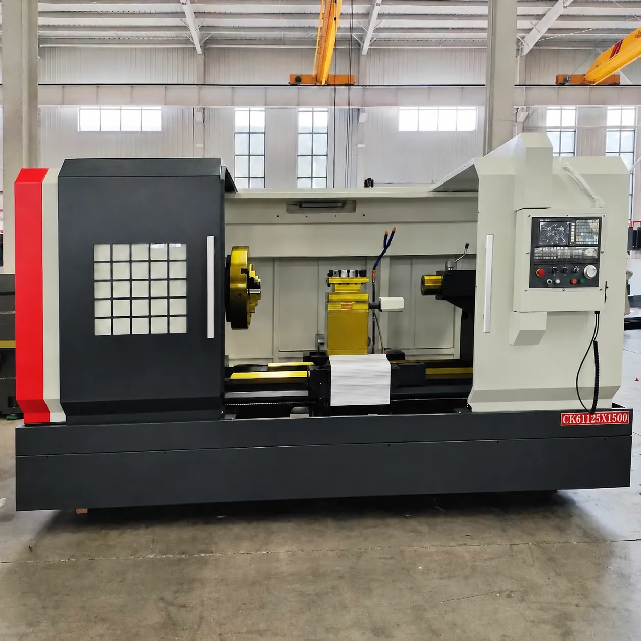
Quenching and tempering use two mesh-belt furnaces. Machining capability includes 60+ machining centers and 70+ CNC machines. Connect the selected heat treatment and machining requirements to the material and component features, keeping the actual equipment capabilities distinct from the acceptance required of a particular railway part.
Surface treatment and assembly scope
Available directions include e-coating, zinc plating, mirror polishing, sand blasting, shot blasting and assembly. Choose the treatment for the selected material and surfaces, and define any assembly interfaces that the work must address. This connects appearance and finishing decisions to the component's geometry and its intended railway function.
Inspection methods and acceptance coverage
Inspection methods include MT, UT, RT and CMM, with 100% visual and 100% gauge inspection. Specify the applicable requirement from ASTM, AISI, DIN, BS, JIS, NF or AS and agree which methods and criteria are needed for the part. Material, drawing tolerances and the intended component function should govern that acceptance discussion.