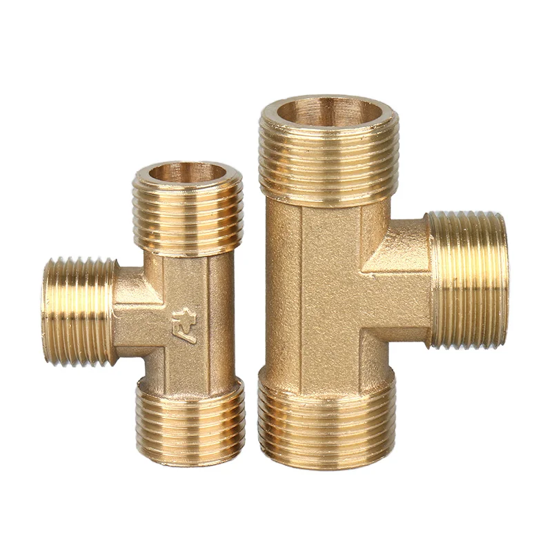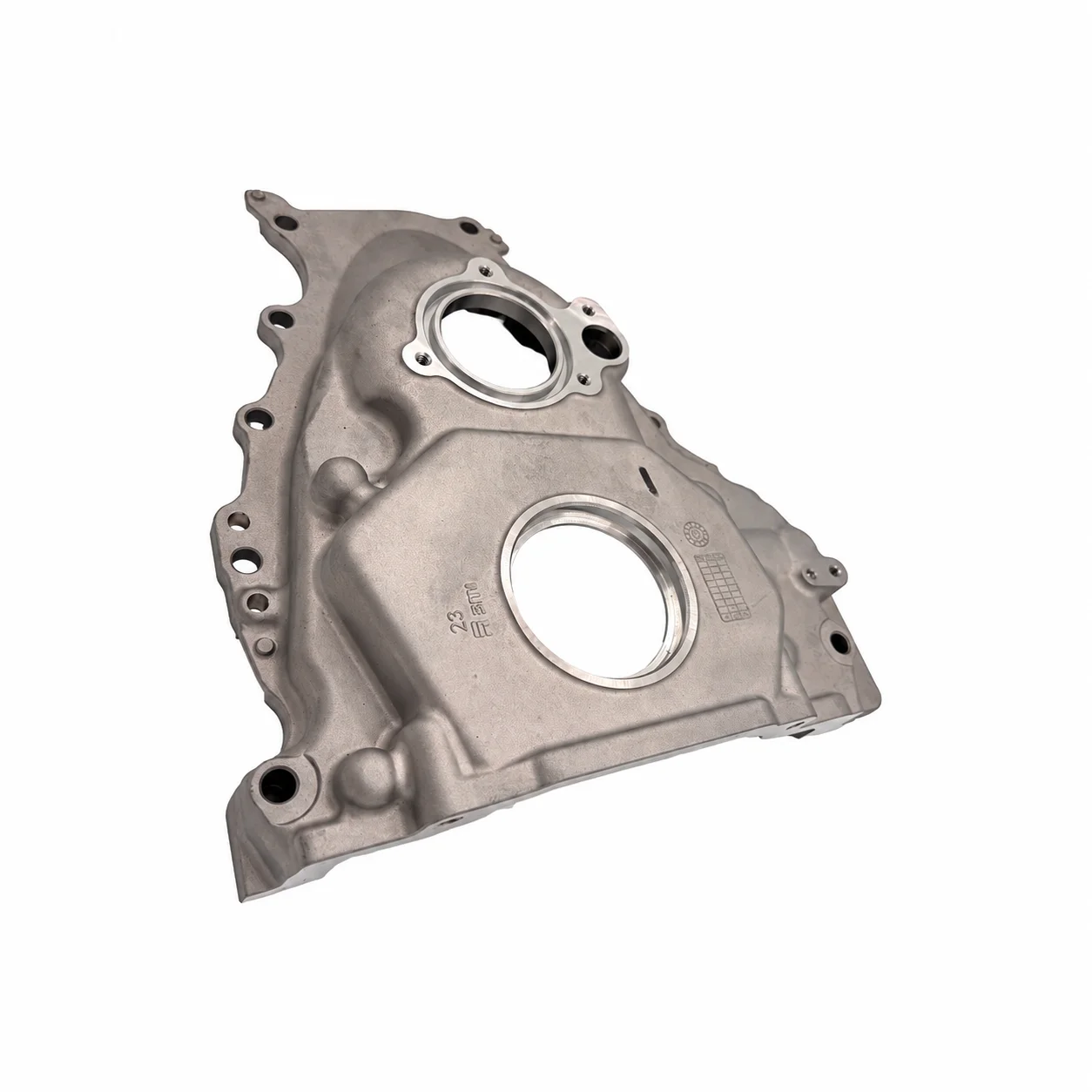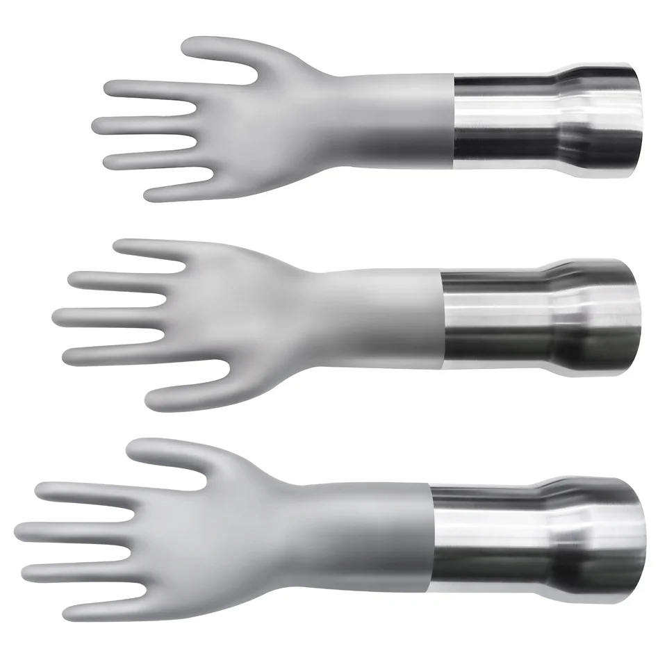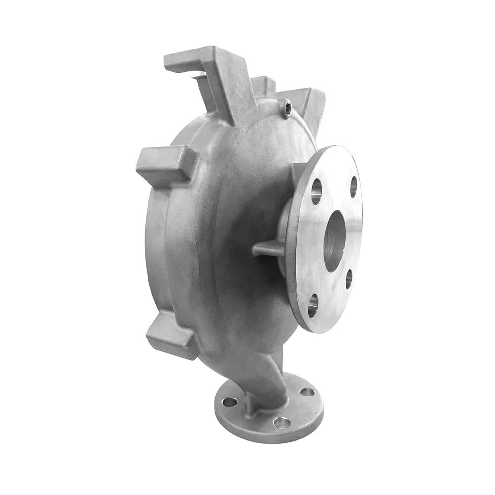
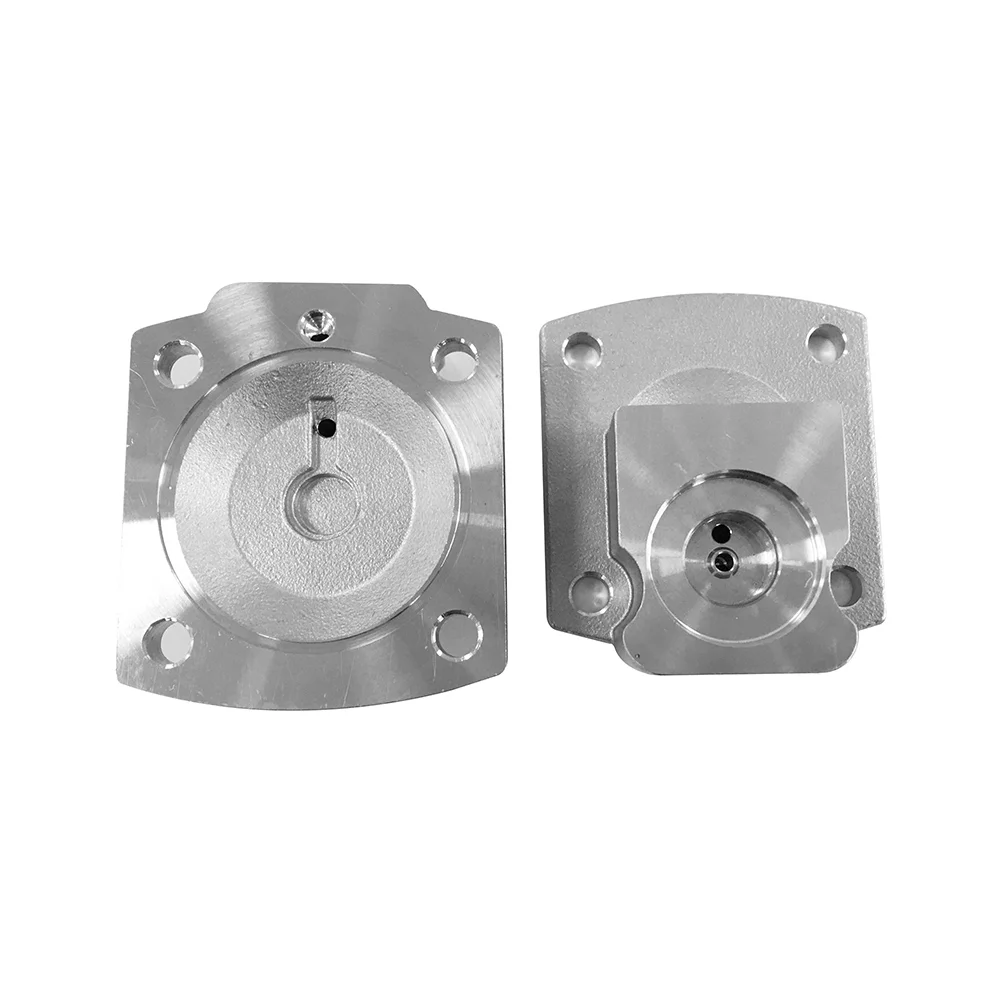
OEM Carbon-Steel/304/316L Stainless-Steel Lost-Wax Investment Castings | CNC, CT4–CT6 and Electroplating
Let’s define your requirement
Send a product link, drawing or short brief. We’ll work through the details with you.
- Confirm the specificationGrade or model, size and intended use.
- Define your orderQuantity, finish or configuration, and samples.
- Agree the quotation scopeIncluded work, key checks and delivery needs.
-
Surface FinishPlatedAlloy Grade316L , 304
-
MaterialStainless Steel ,304,316L
-
DimensionsCustmer's DrawingsProcessInvestment Casting + CNC Machining
-
ApplicationIndustryDie Casting MethodPrecision Die Casting
-
ToleranceCT4-CT6MOQ500pcs
-
Drawing format2D/(PDF/CAD)3D(IGES/STEP)Surface FinishElectroplating
-
Machining ProcessMachining Center
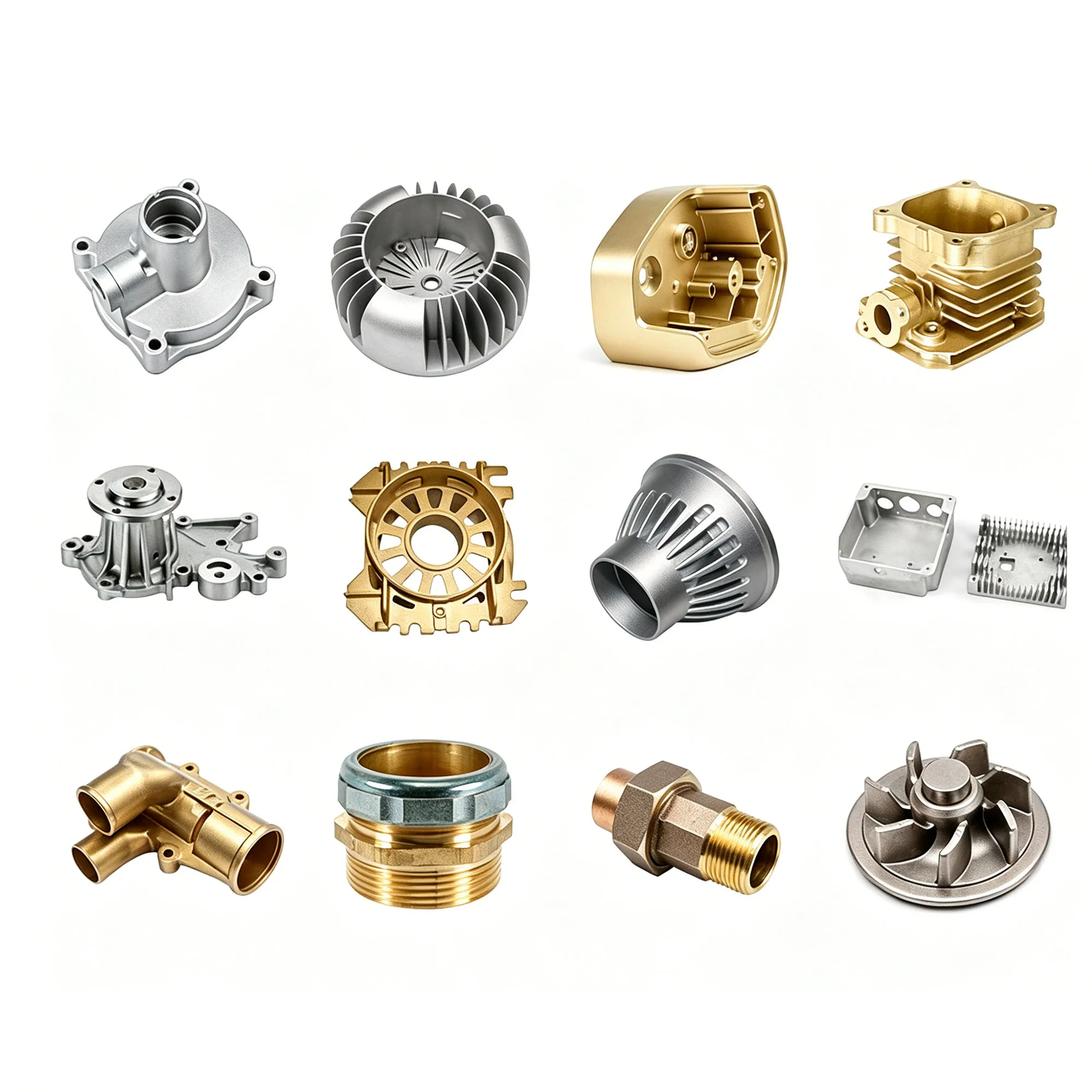
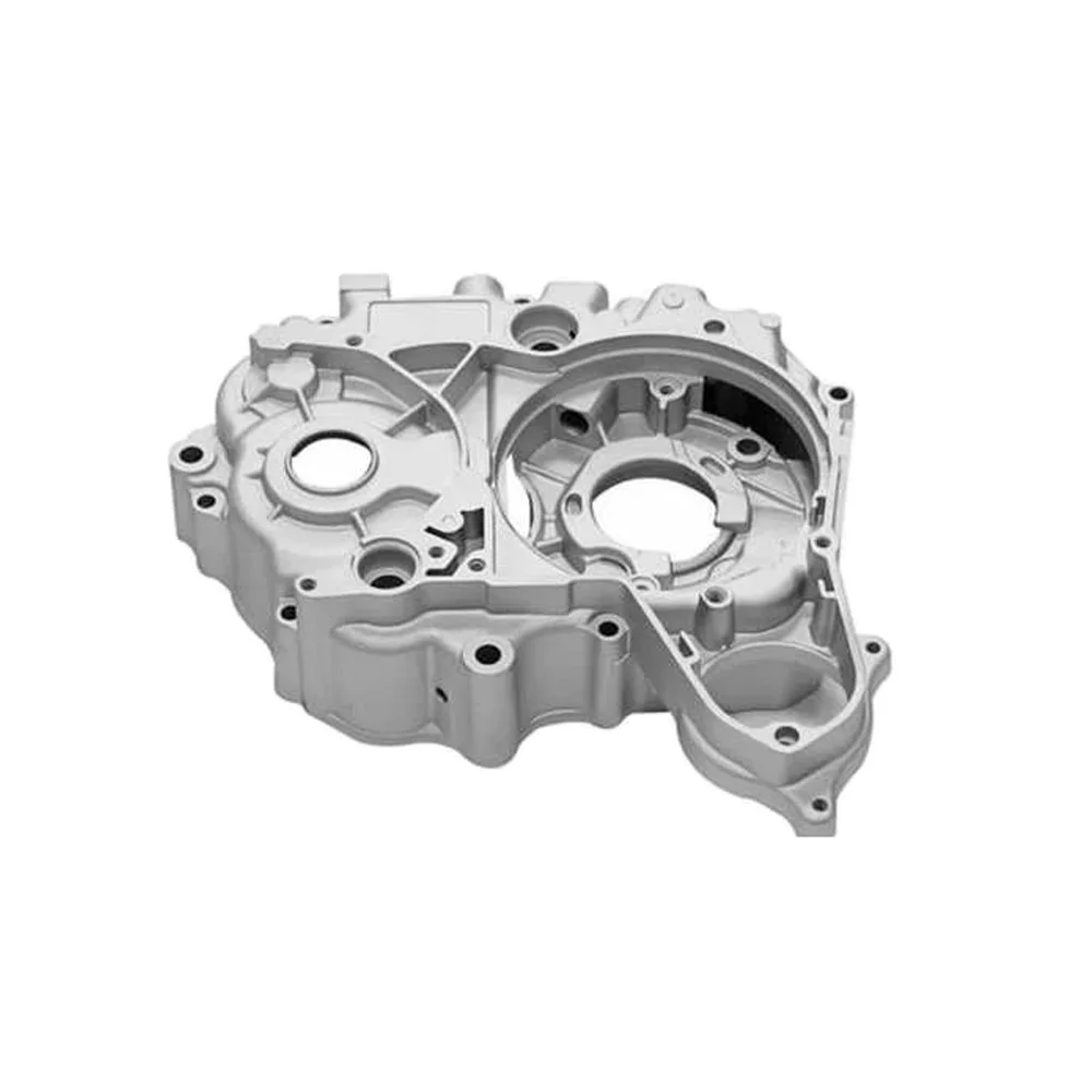
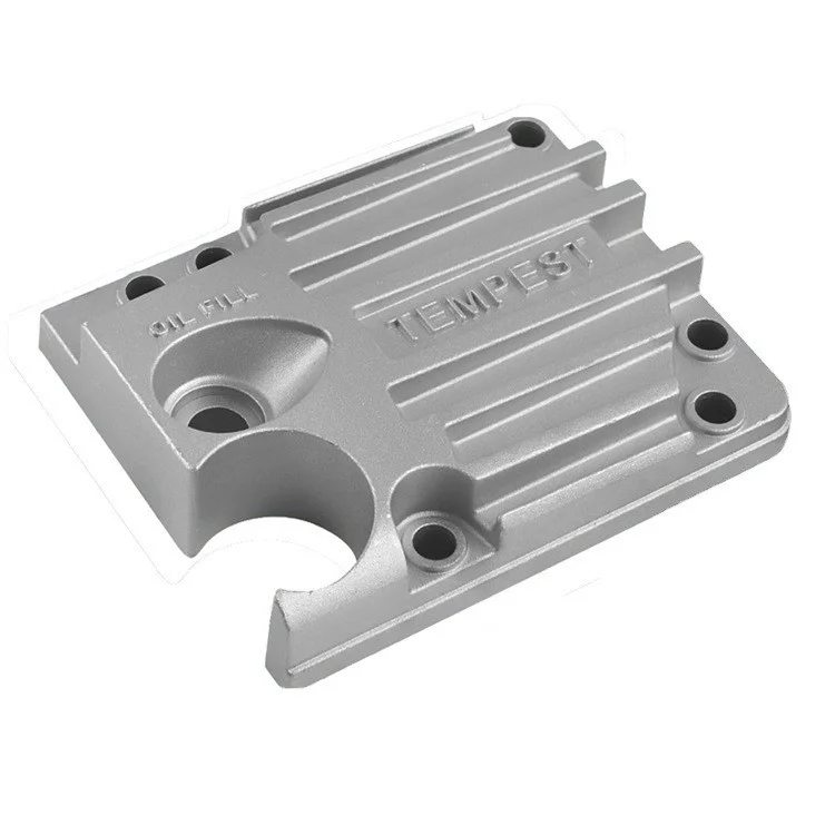
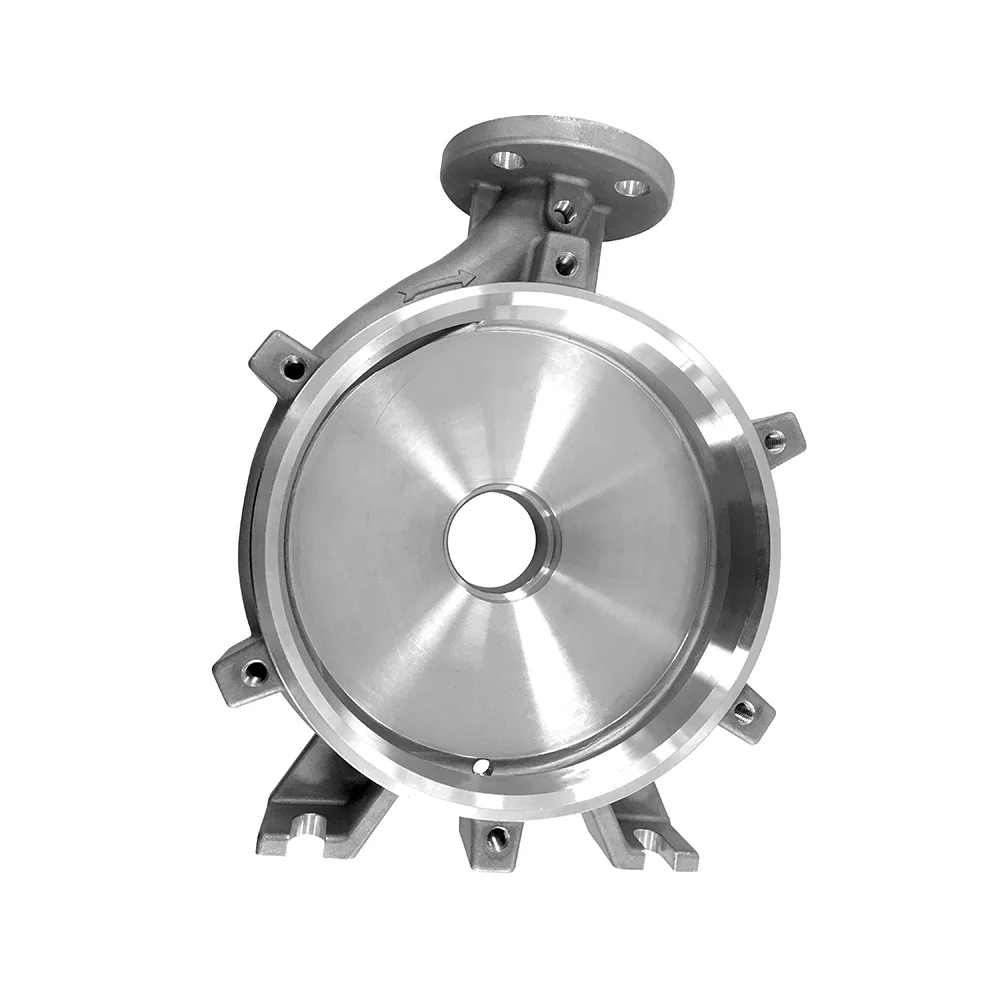
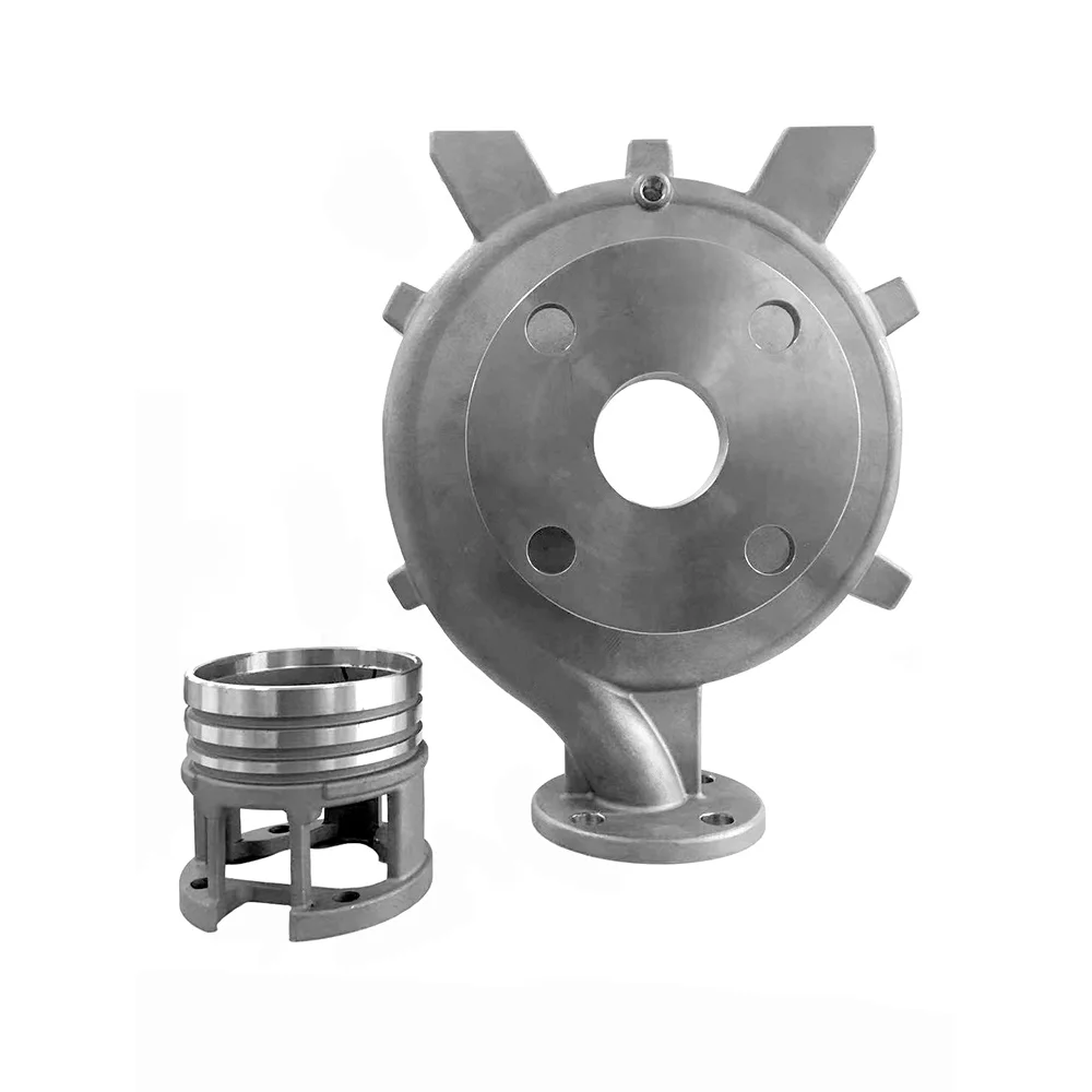
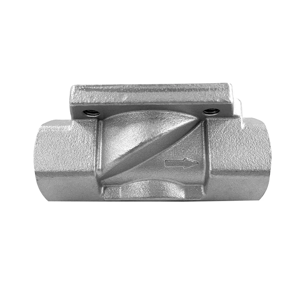
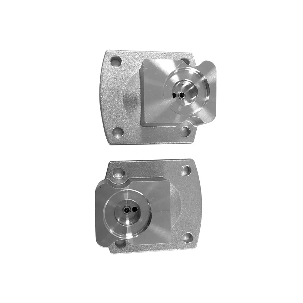
OEM industrial component work includes carbon-steel and 304/316L stainless-steel material directions through lost-wax investment casting and CNC machining. Dimensions follow the customer drawing, with a CT4–CT6 tolerance reference. Precision-die-casting and machining-center directions are also available, with the actual material, component and manufacturing route to select.
Selected steel grade and manufacturing direction
Define the actual carbon-steel or stainless-steel designation and the component geometry being requested. Agree the investment-casting or precision-die-casting route for that particular material and part. Connect the selected process to the required supplied condition, identifying the cast areas and interfaces needing further machining within the industrial component.
Drawing-controlled dimensions and CT4–CT6
Establish the dimensions and manufacturing scope governed by the selected tolerance reference. Identify the important cast geometry and the interfaces requiring CNC work. Agree the measurement basis and acceptance for those controlled areas, relating the drawing requirements to the actual material, route and finished component condition.
Machined areas and electroplated surfaces
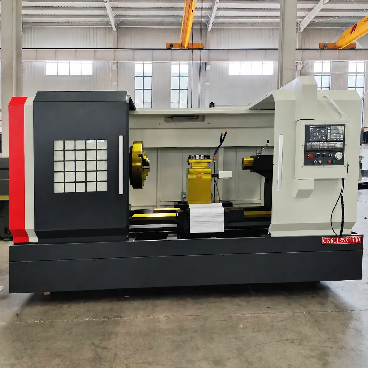
Define the actual CNC/machining-center work and the finished dimensions of its interfaces. Identify which areas require electroplating and the supplied-surface condition needed there. Relate those requirements to the selected steel and component geometry, agreeing dimensional and visual acceptance after the included manufacturing and surface operations.
PDF, CAD, IGES and STEP input
Supported drawing directions are 2D PDF/CAD and 3D IGES/STEP. Use the selected input to define the actual industrial part and its material designation. Connect its geometry, controlled dimensions and treated areas to the chosen manufacturing route, establishing the finished-part requirements and inspection acceptance for that OEM component inquiry.