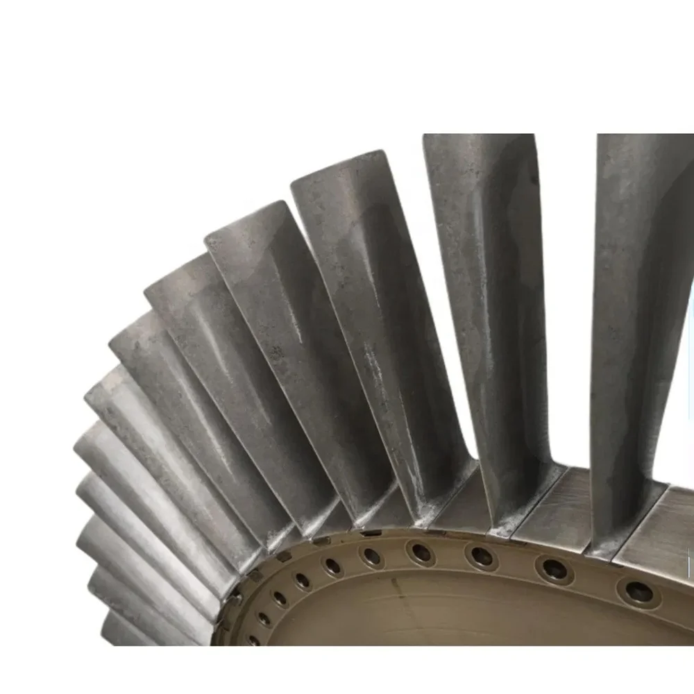
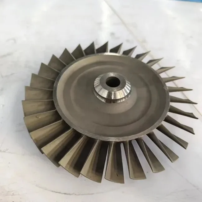
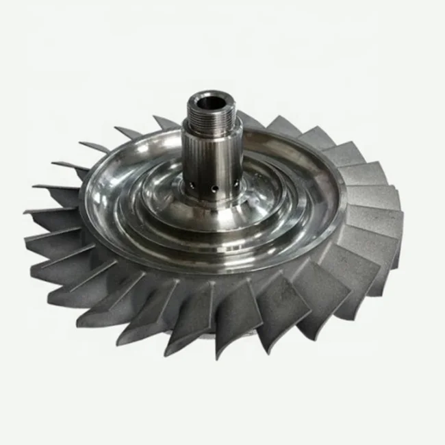
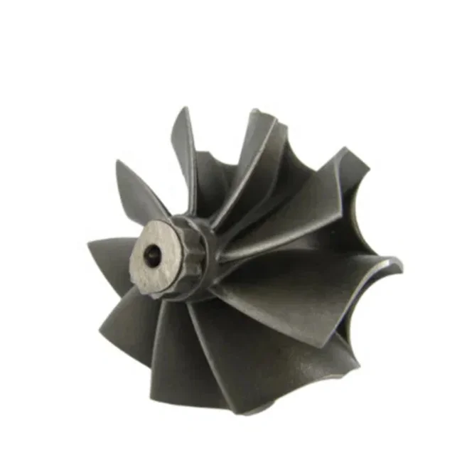
Custom Silica-Sol/Water-Glass Vacuum Lost-Wax Investment-Cast Turbocharger Parts | Precision Machining
Let’s define your requirement
Send a product link, drawing or short brief. We’ll work through the details with you.
- Confirm the specificationGrade or model, size and intended use.
- Define your orderQuantity, finish or configuration, and samples.
- Agree the quotation scopeIncluded work, key checks and delivery needs.
-
Surface FinishPainted , Polished
-
ItemCustom Investment Casting
-
MaterialSteel/ Brass/ Bronze/ TitaniumSurface treatmentPolishing, Plating, Painting, Power Coating
-
ProcessSilica Sol, Water Glass, PlasterSampleFree samples can be sent after paying the mold fee
-
MOQ100 PiecesDrawing Format2D: PDF, DWG, DXF 3D: STEP, STP, IGS
-
PackingCarton, Plywood CaseShippingBy Courier/ Air/ Railway/ Sea
-
PaymentT/T, PayPal, Alipay, L/C, Western Union
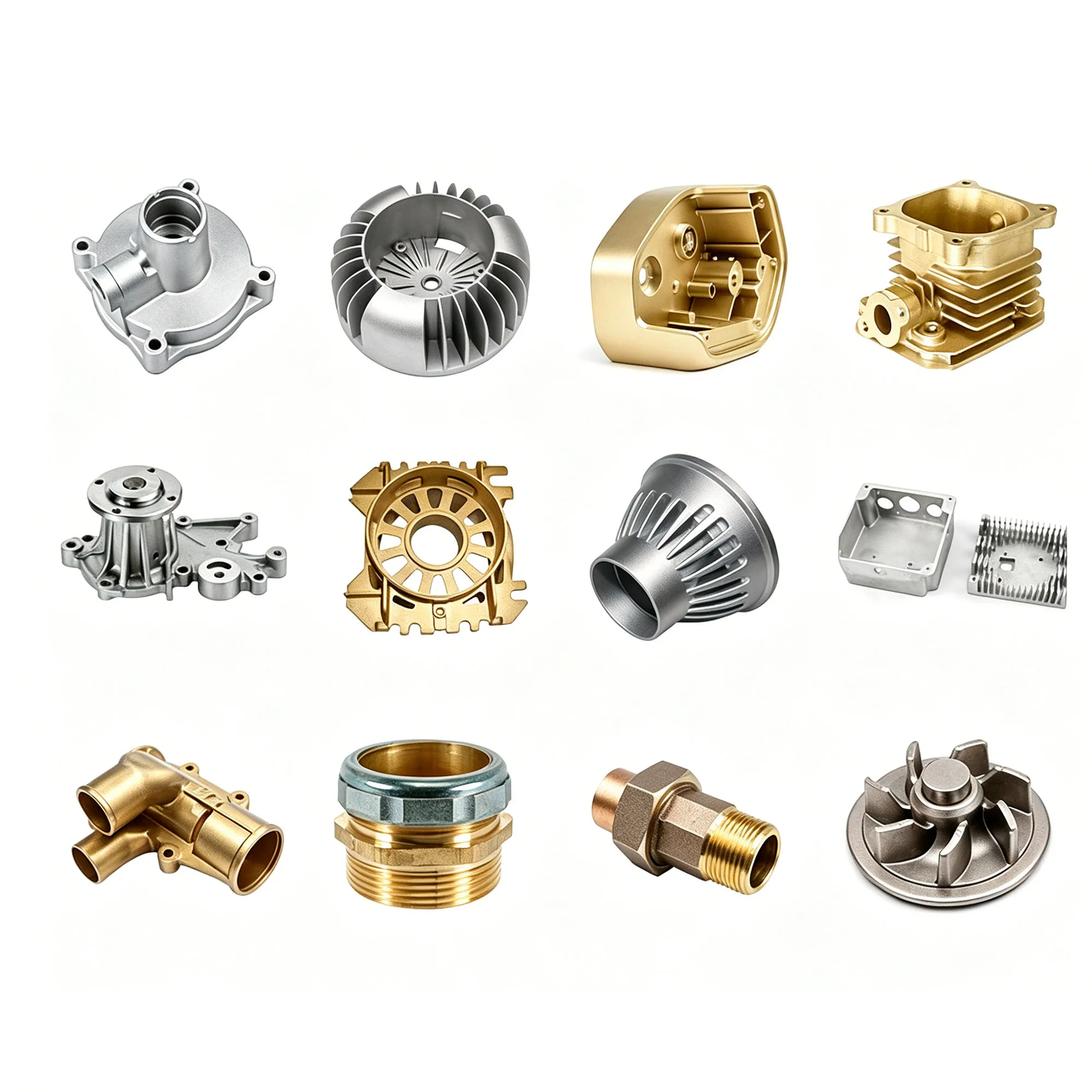
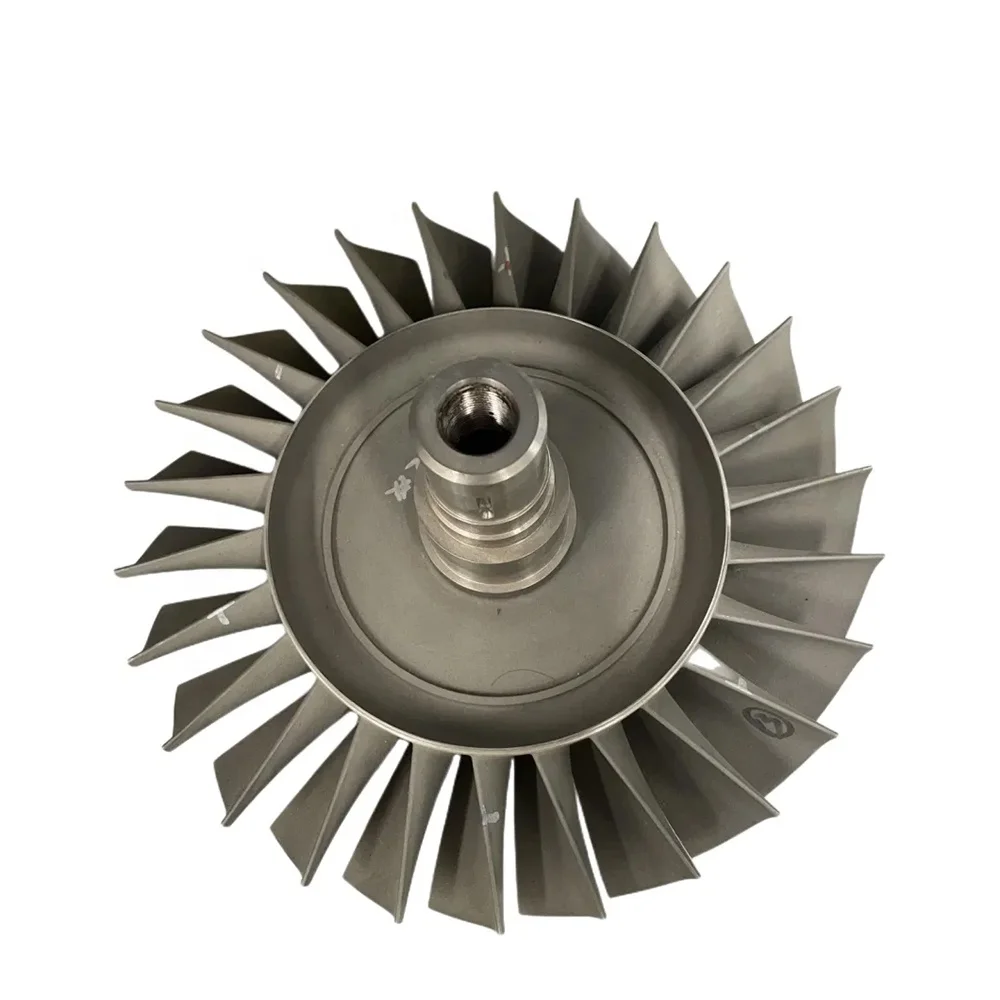
Custom turbocharger parts combine vacuum lost-wax investment casting with precision machining. Silica-sol, water-glass and plaster process directions are available, alongside steel, brass, bronze and titanium material choices. The actual part requires a selected material and casting route, rather than an assumption that every material and process forms the same configuration.
Match the turbocharger component to its route
Describe the component geometry and the conditions of its intended turbocharger use when selecting the casting approach. Establish whether silica-sol, water-glass or plaster work is appropriate to that request. Keep the chosen grade and process together in the part definition so that the casting and precision-machining scope can be reviewed coherently.
Coordinate machining with the surface choice
Polishing, plating, painting and powder coating are surface directions for the custom work. Identify the surfaces requiring precision machining and the surfaces requiring the selected treatment. Agree the finished condition and controlled dimensions with those operations in view, particularly where a treated surface also forms part of the dimensional acceptance.
Use the accepted two- and three-dimensional inputs
Geometry inputs include 2D PDF, DWG and DXF, together with 3D STEP, STP and IGS. Use the appropriate files to identify the actual part, material selection and machining requirements. Agree the tooling and sample arrangement for that component, then establish the inspection acceptance that will be used to review its dimensions and chosen surface condition.