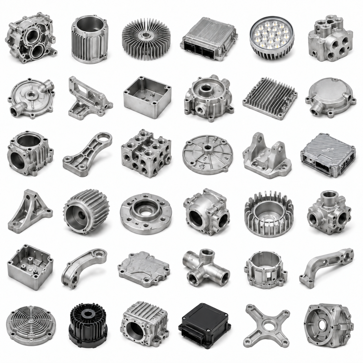
OEM Precision Aluminum-Alloy Die/Investment Castings | CNC-Machined Motor and Large Industrial Accessories
Let’s define your requirement
Send a product link, drawing or short brief. We’ll work through the details with you.
- Confirm the specificationGrade or model, size and intended use.
- Define your orderQuantity, finish or configuration, and samples.
- Agree the quotation scopeIncluded work, key checks and delivery needs.
-
Surface FinishAnodized , Powder Coated
-
Materialaluminum /iron /steel/ zamac/cooper etcProcessCasting +Machining(if Need)+surface Treatment
-
Surface treatmentPowder Coating /Painting / CNC /Anodizing etc.CertificationISO9001/TS16949/RoHS
-
Drawing format2D/(PDF/CAD)3D(IGES/STEP)APplicationPunching High Precision Cold Runner Steel Abs Plastic Pp Mold Moulds
-
ApplicatioNExtrusion Round Preform Rubber Silicone Injection Mould For IndustryApplicatiOnCarbon Zinc Sand Brass Aluminum Alloy Steel Die Casting Service Parts
-
ApplicatIonStainless Steel Gravity Round Valves Casting Services Powder ProductApplicaTionSteel Pp Abs Plastic Moulds Magnesium Gravity Die Casting Service
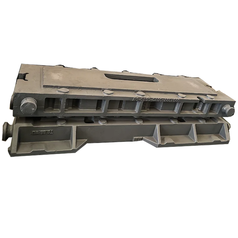
Customized OEM aluminum-alloy parts are offered for motor and large industrial-accessory inquiries, with die-casting, investment-casting and CNC-machining directions. The work scope combines casting, machining when needed and surface treatment. Powder coating, painting and anodizing are finish choices to select for the actual material and component.
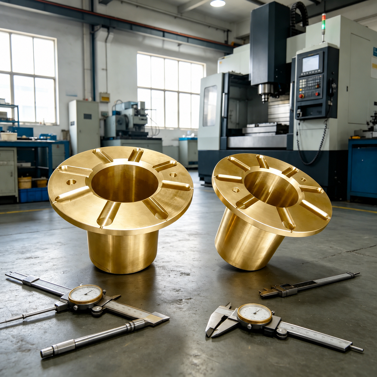
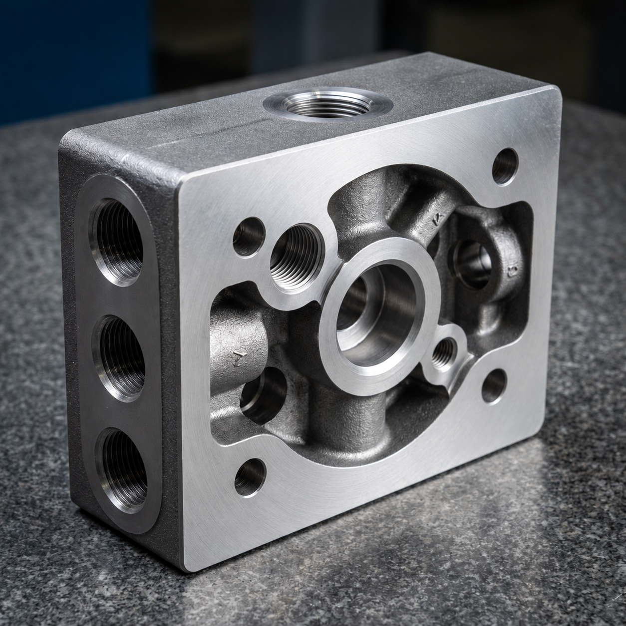
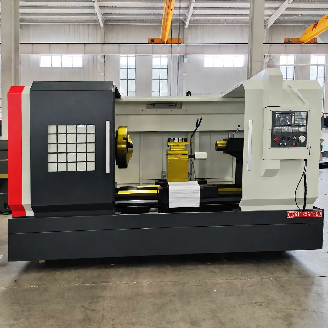
Motor accessory geometry and CNC work
Define the actual accessory, its selected alloy and the casting route needed for its geometry. Identify the interfaces requiring CNC machining and the finished fit relevant to the motor or industrial application. Agree the dimensional acceptance for those areas, connecting the cast component and further machining within a specific manufacturing task.
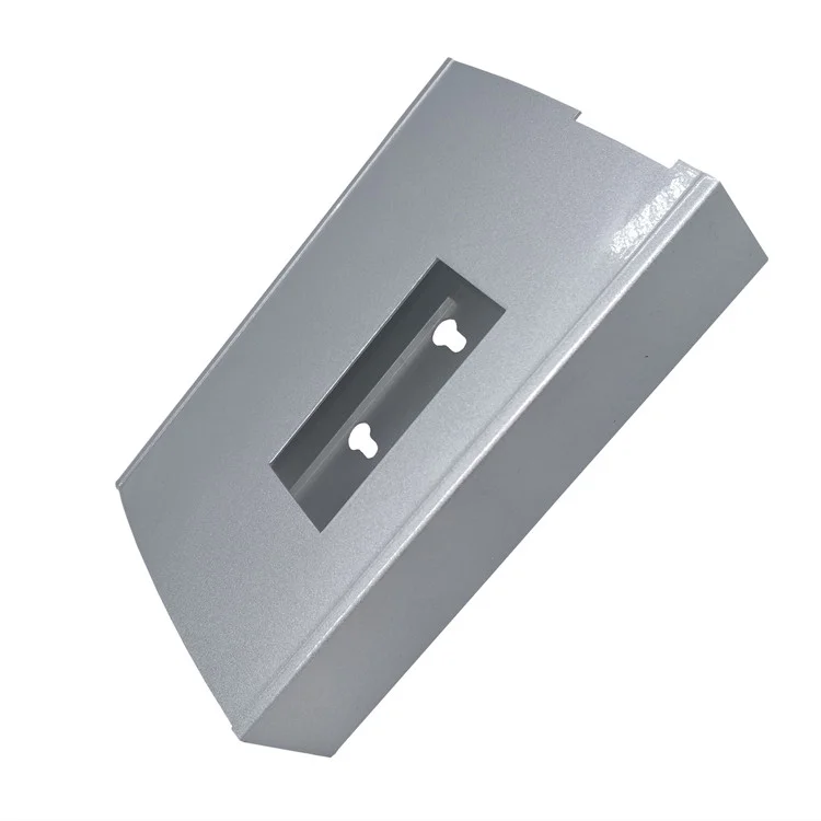
Coating, paint and anodized areas
Select the surface direction for the actual material and required appearance. Define the treated areas and the finished condition expected after powder coating, painting or anodizing. Relate their visual and dimensional acceptance to the important machined interfaces, establishing which surfaces need to meet the component's functional and appearance requirements.
Additional metal and tooling inquiry directions
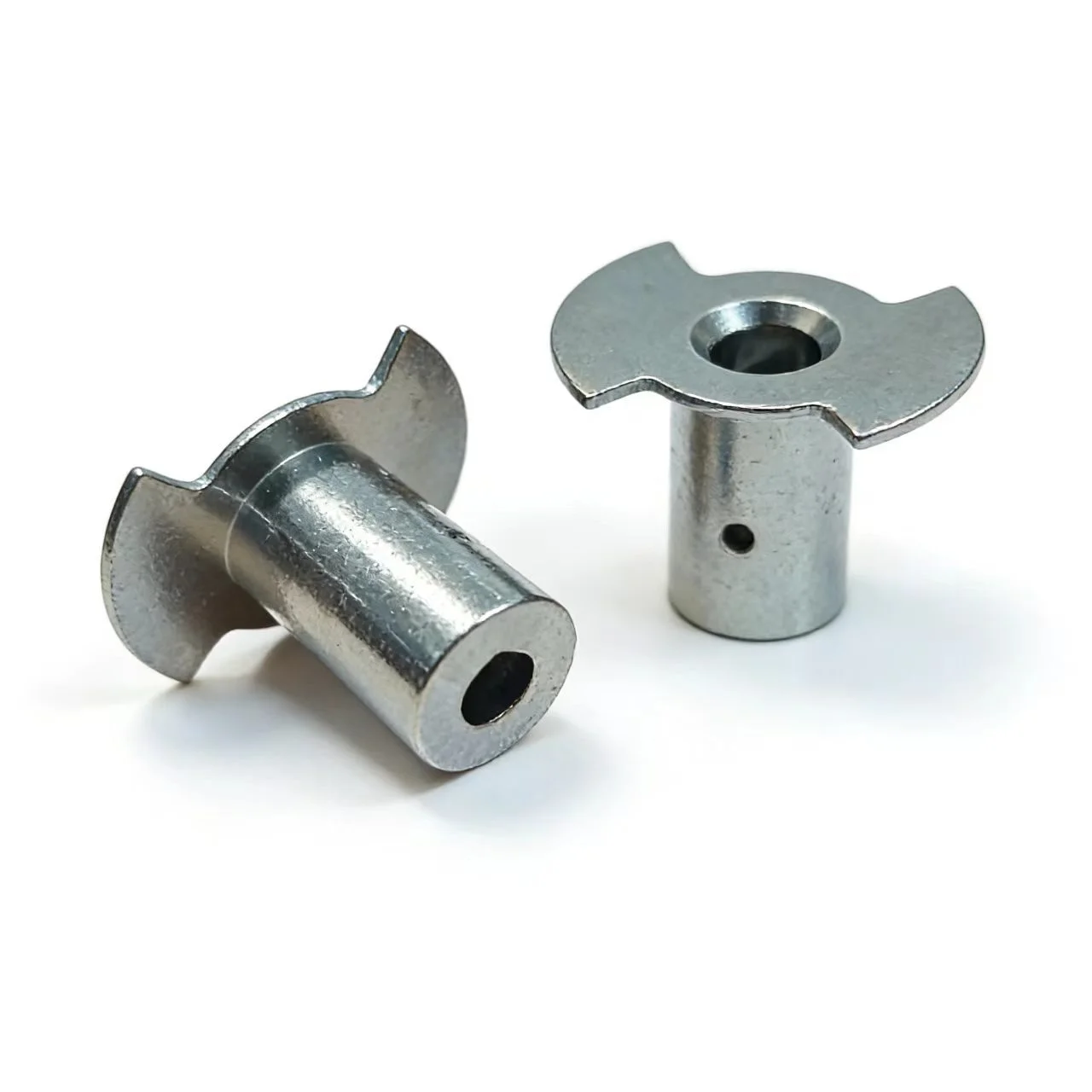
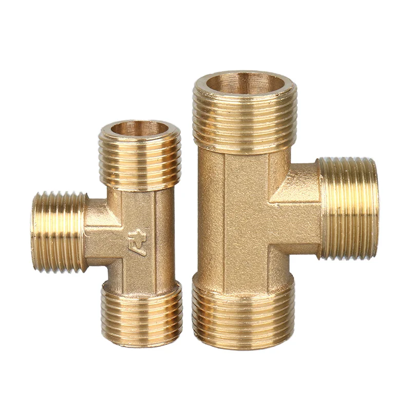
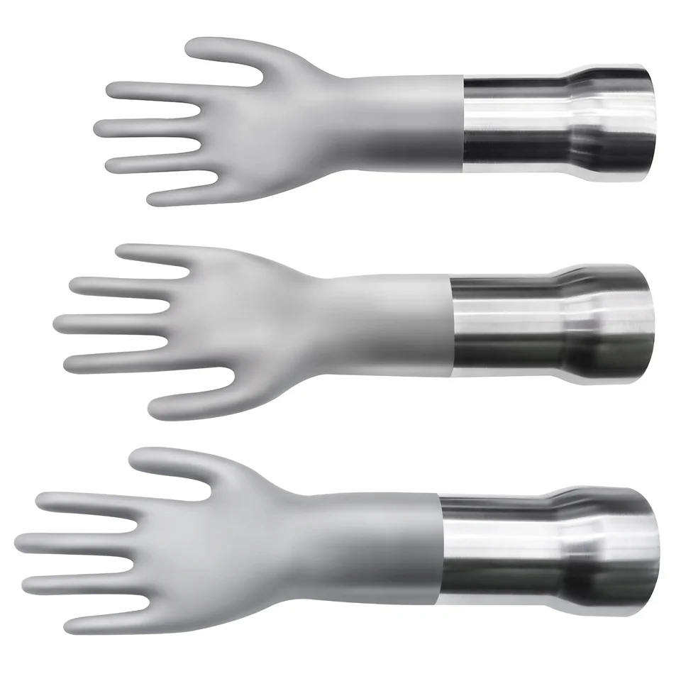
Material directions also include iron, steel, zamac and copper, with brass, zinc, stainless-steel and magnesium casting inquiries. Other directions cover sand/gravity casting and valve-related parts, punching/cold-runner steel/ABS/PP molds, extrusion/preform and rubber/silicone injection-mold work. Establish the actual component or tooling object before selecting its material and manufacturing route.
Drawing files and supplied-object acceptance
Inputs include 2D PDF/CAD and 3D IGES/STEP. Define the geometry, controlled dimensions and supplied condition for the actual part or mold task. Connect that definition to its selected casting route, CNC requirements and material-appropriate finish. Agree the inspection acceptance needed to evaluate that specific deliverable within the OEM request.