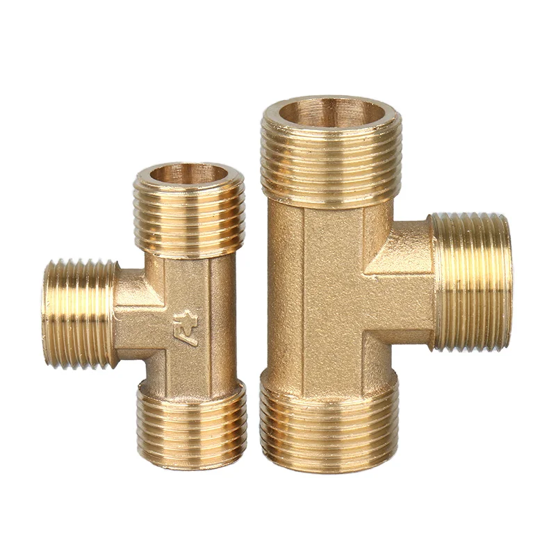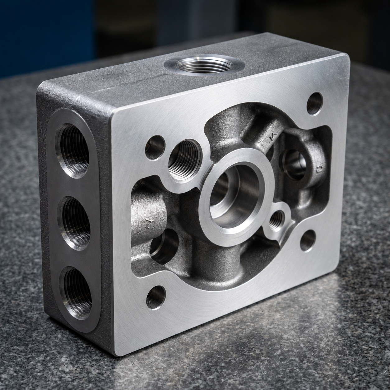
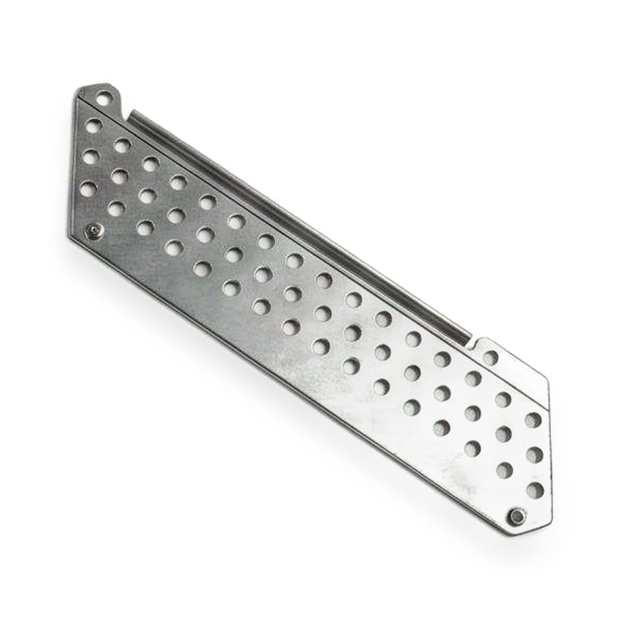
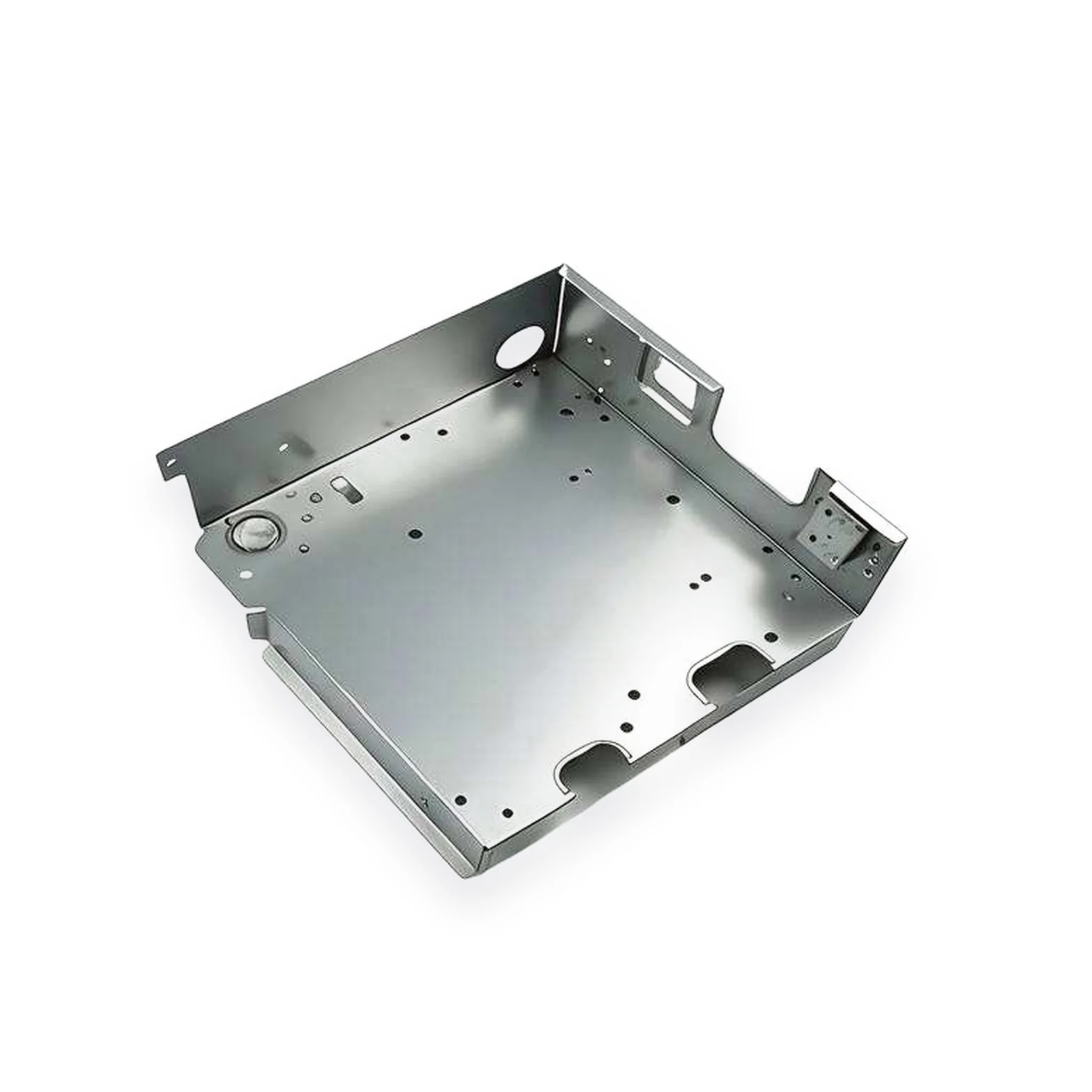
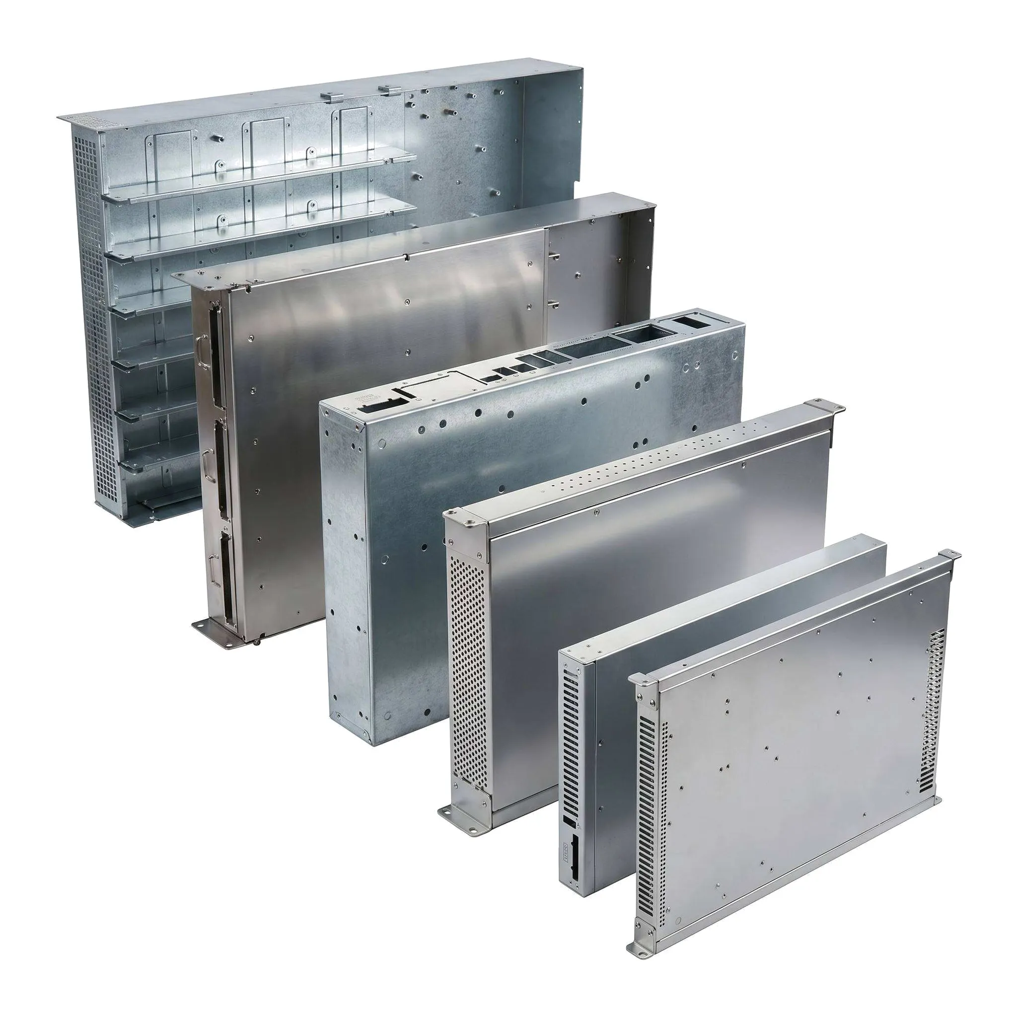
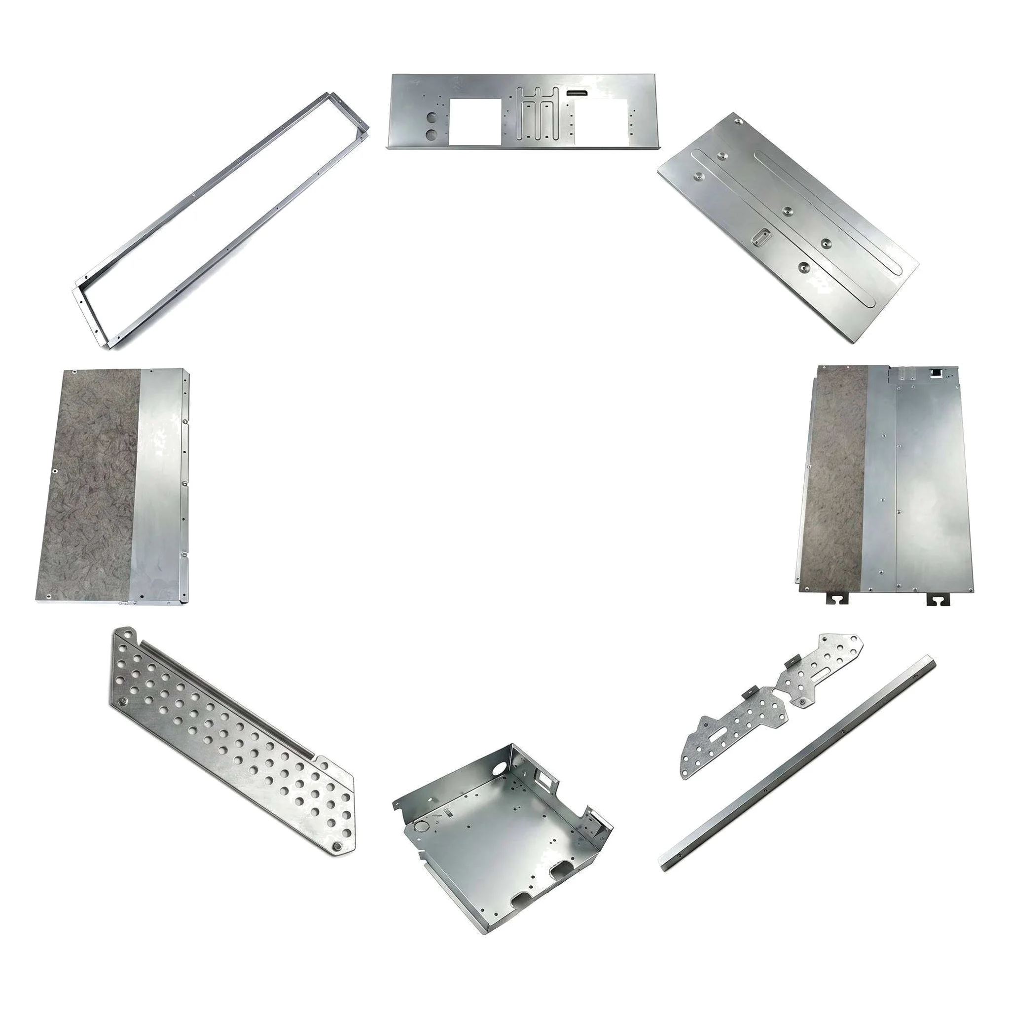
Custom Zinc Alloy Zamak Hardware Lock Parts and Industrial Fittings with Drawing-Confirmed +/-0.01mm Tolerance
Let’s define your requirement
Send a product link, drawing or short brief. We’ll work through the details with you.
- Confirm the specificationGrade or model, size and intended use.
- Define your orderQuantity, finish or configuration, and samples.
- Agree the quotation scopeIncluded work, key checks and delivery needs.
-
Component FormFitting / JointSurface FinishPowder Coated , Polished
-
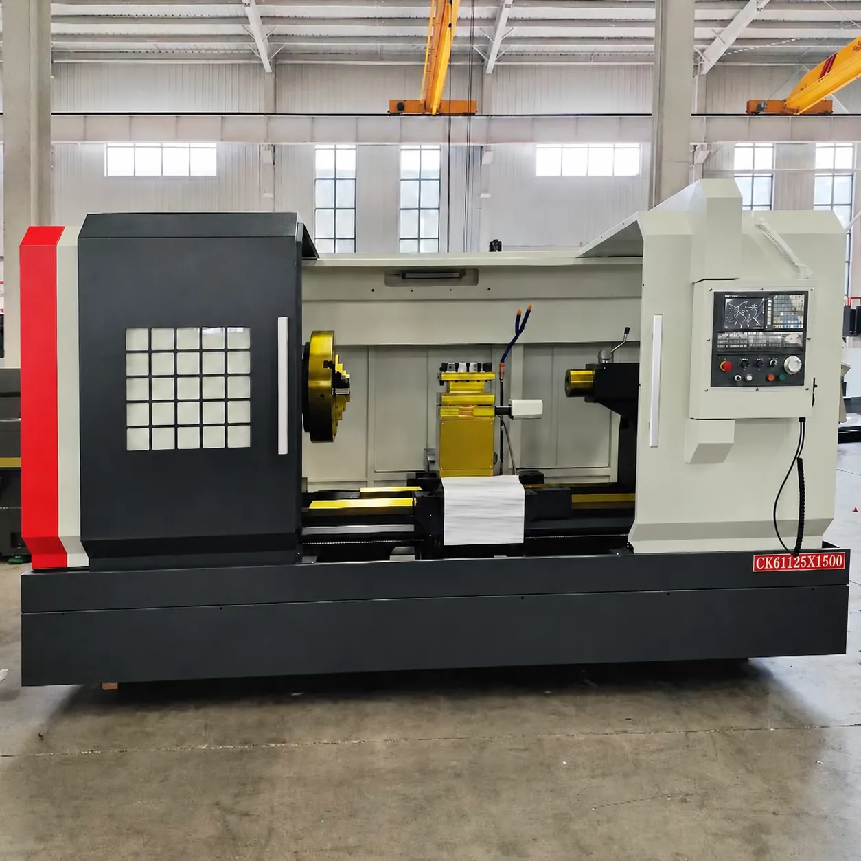
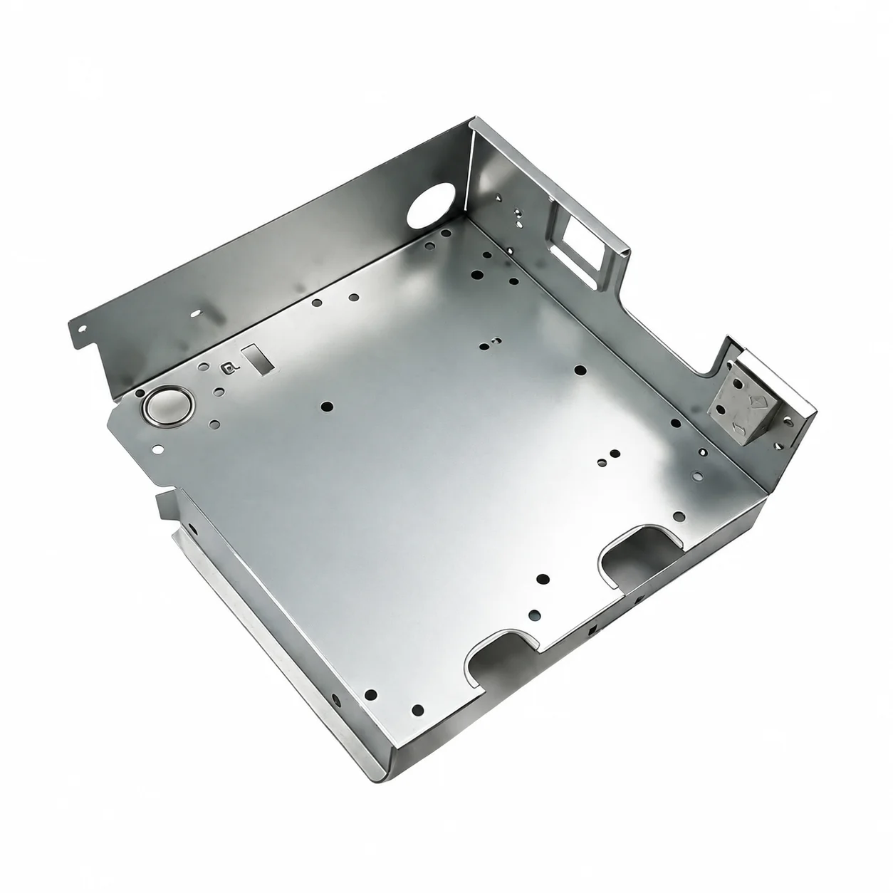
MaterialZincProcessLaser Cutting, CNC Bending, Welding, Stamping
-
Surface treatmentPowder Coating, polish, brush, anodized, galvanizedCertificationISO 9001, ISO 14001, ISO 45001, IATF 16949
-
Drawing FormatDWG, DXF, STEP, IGES, PDF, AIMOQ10 Pieces, Sample from 1 Piece
-
Tolerance+/-0.01mm, Confirmed per DrawingDelivery Time7 Days for 1-10 pcs
-
Quality ControlFAI, In-Process and Final InspectionOEM/ODMOEM and ODM Available
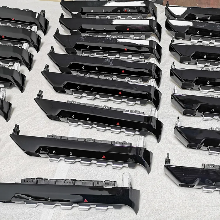
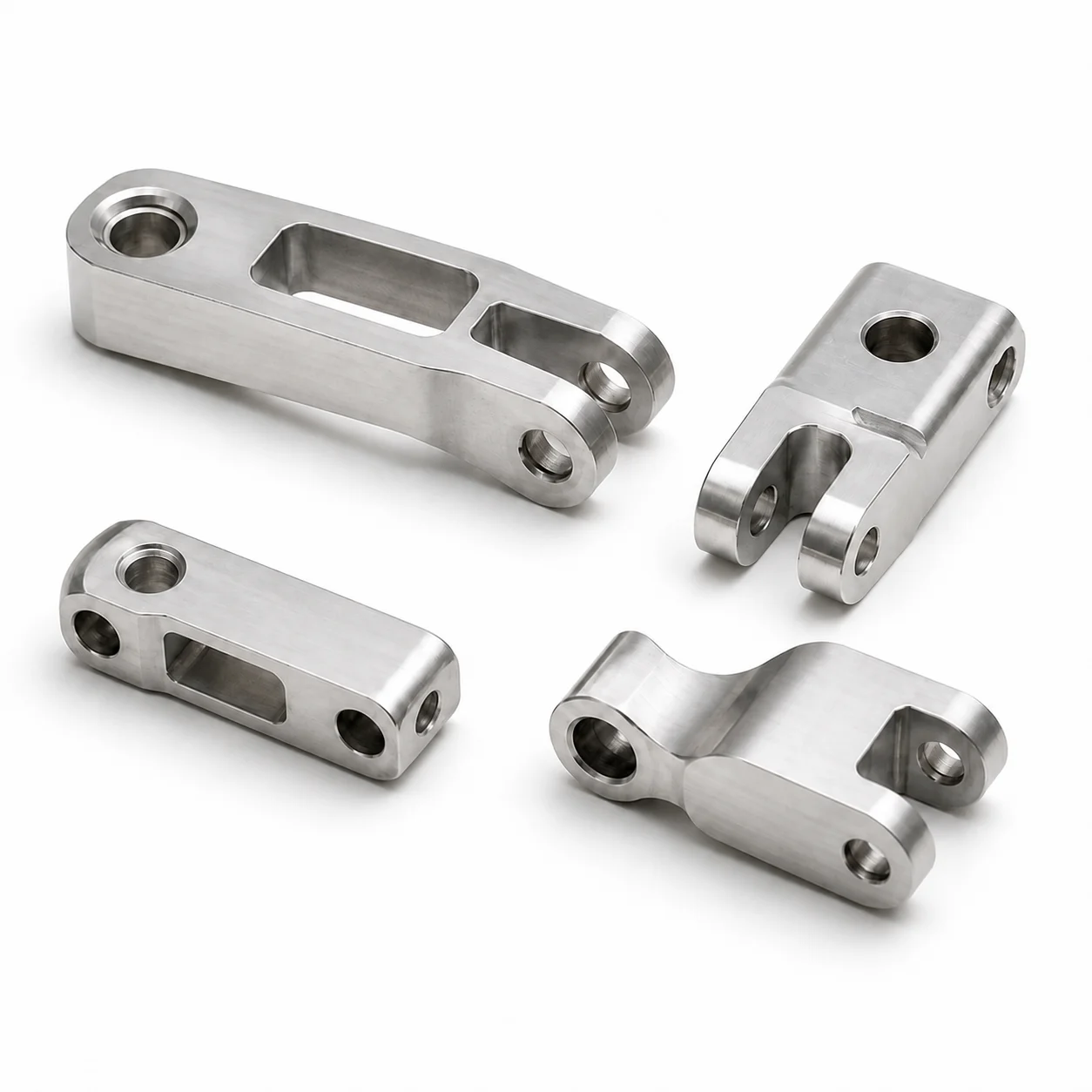
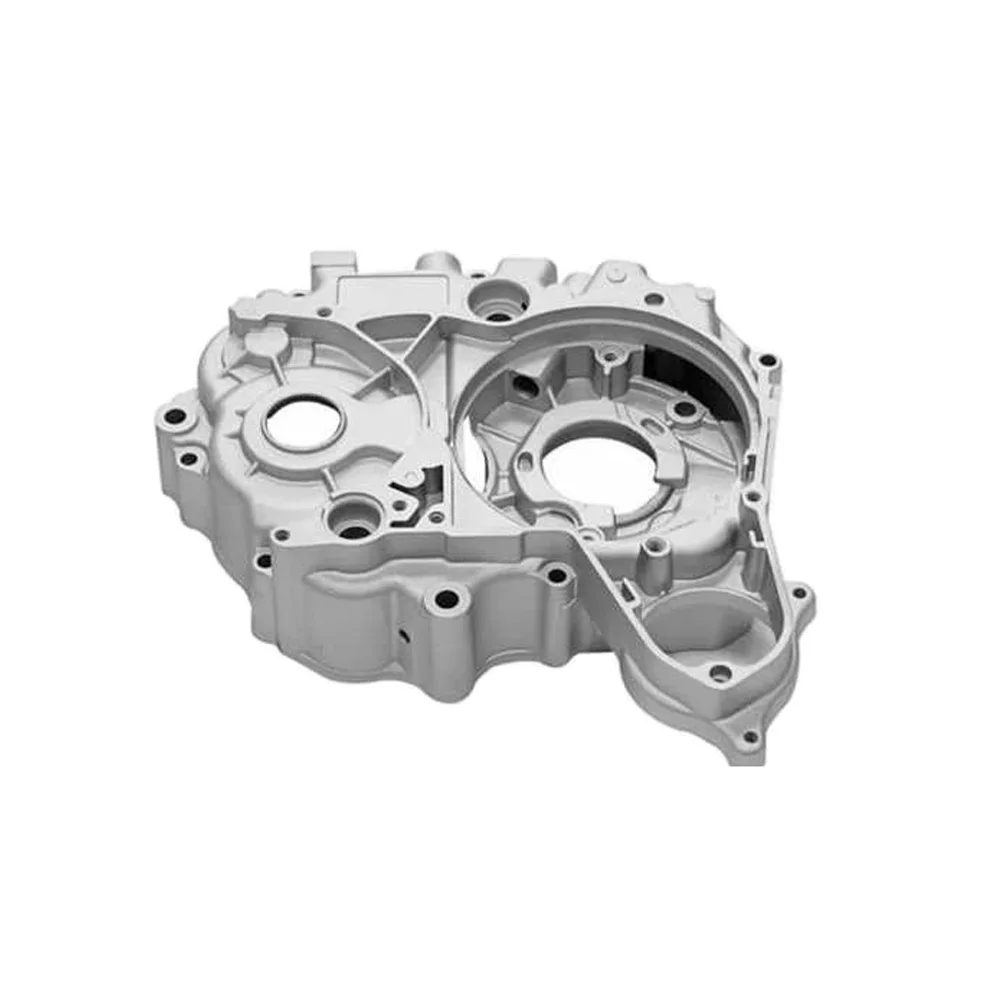
Custom zinc-alloy hardware starts with the lock part or industrial fitting that the project actually requires. This Zamak component offering supports OEM and ODM inquiries, with sample quantities available and the precision requirement confirmed against the individual drawing.
Define the lock part or industrial fitting
Identify the component geometry and its relationship to the surrounding hardware assembly. A lock-related part and an industrial fitting can require different dimensions even when both use zinc alloy. Keep the selected Zamak material and the component drawing together so the proposal addresses the intended part rather than a broad hardware category.
Agree the manufacturing operations
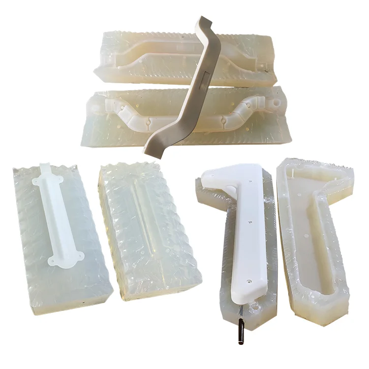
The work should identify the casting or fabrication route appropriate to that geometry. Discuss any laser cutting, CNC bending, welding or stamping required for the component, and distinguish those operations from the finished part definition. This keeps the scope clear without assuming every operation belongs in a single sequence for every zinc-alloy design.
Choose the zinc-alloy surface condition
Galvanizing, powder coating, polishing, brushing and anodizing are treatments to discuss for the selected material and part. Agree the required finish and its applicability before accepting the component proposal. Identifying the relevant surfaces also gives the hardware inquiry a clearer appearance and finishing scope.
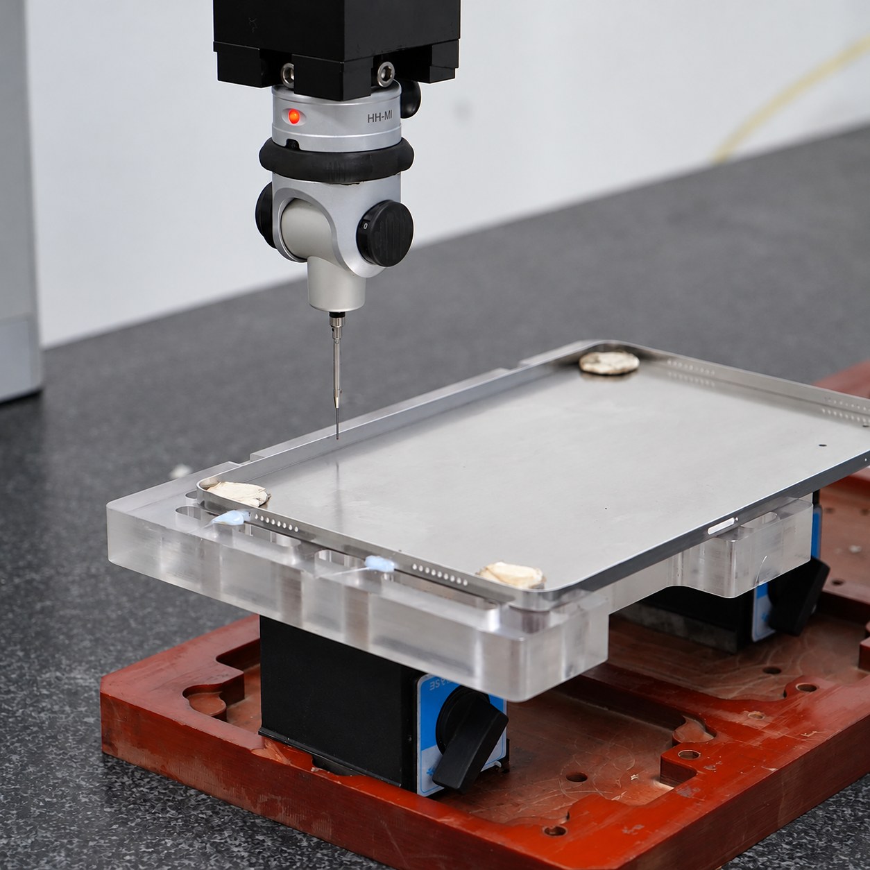
Inspect the dimensions that carry the tolerance
The +/-0.01mm tolerance is confirmed per drawing, so identify the features that require that precision. FAI, in-process checks and final inspection provide the stated quality-control stages for the discussion. DWG, DXF, STEP, IGES, PDF and AI files can carry the component definition, while sample review should use the same geometry and acceptance criteria intended for the hardware order.