
Define the finished interfaces before requesting machining
A casting plus CNC machining enquiry should identify which features must be machined, the drawing requirements they must meet and the condition in which the finished component will be accepted. Do not rely on a general request for “precision machining.” Mark datums, bores, threads, mating faces and other functional relationships so that the proposed scope can be reviewed against the actual assembly.
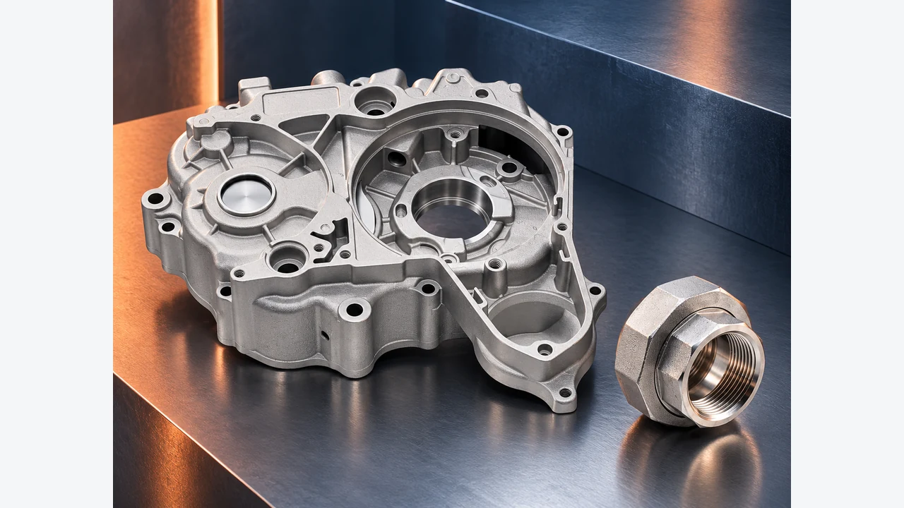
The catalogue includes both cast and machined component references. A photograph can show a smooth face or threaded opening, but it does not establish a tolerance, thread standard or inspection method. The selected listing is a starting reference. The current drawing and agreed requirements define the ordered part. Use the CNC-machined component collection to locate examples and identify the relevant product URL in your enquiry.
This article is a drawing and purchasing checklist. It does not specify machine settings, universal machining allowances or guaranteed process capability. Those decisions require review of the actual part, material and proposed operations. The buyer's task is to make the required outcome clear enough that the supplier can explain the proposed scope and any unresolved questions.
Separate as-cast surfaces from machined features
Begin by identifying the condition of each important region. Some surfaces may remain as cast; others may need machining, finishing or protection. Mark the transition between those conditions where it matters. A blanket instruction to machine the part can leave uncertainty about surfaces that should remain untouched, while a vague note about “machined faces” may not identify every interface that controls assembly.
Show the part envelope and internal features as well as the obvious external faces. A photograph taken from one side may hide a bore, recess or mounting relationship. If separate casting and machining drawings are used, identify both revisions and explain how the documents relate. Confirm which document governs the finished component and which describes an intermediate supply condition.
Where the buyer will perform later machining, describe the handoff instead of asking for a finished part by default. Identify the features that must already be established, surfaces reserved for later work and any required identification. Ask for the proposed intermediate condition to be reviewed. Do not infer a machining allowance from another component's description or from the apparent thickness of a photographed wall.
State the scope in plain words
A short sentence can prevent a major misunderstanding: identify whether the enquiry is for an unfinished casting, a casting with selected machined interfaces or a fully machined component to the drawing. Follow that sentence with the controlling documents and a list of excluded or buyer-supplied operations. The quotation can then be checked against a defined supply boundary.
Make the datum scheme and critical dimensions visible
Identify the reference features used to define the component's geometry. If a bore must align with a mounting face or a bolt pattern must relate to another feature, make that relationship explicit on the drawing. A collection of individual size dimensions may not communicate the full assembly requirement. Include the datum scheme and any relevant geometric requirements from the controlled specification.
Distinguish general tolerances from feature-specific limits. If the drawing uses a general tolerance note, identify the applicable reference and revision where required. Put local requirements at the features they control. A tight requirement on one functional bore should not be assumed to apply to every unmarked casting surface, and an unmarked critical feature should not depend on verbal expectations.
Explain why a feature is critical when that context helps the review. A sealing interface, bearing location or mounting relationship may need to be considered with its mating part. Provide the relevant assembly information without replacing the controlled drawing with an informal sketch. If the mating component is needed for an approval check, identify it and ask how it will be made available.
Do not use the same tolerance wording for every part merely to make RFQs look consistent. The requirement should reflect the actual design. If a dimension is still under review, label it as unresolved and identify the approval owner. This is more useful than requesting a quotation against a number that may change before tooling or machining begins.
Specify threads, holes and sealing interfaces completely
A threaded opening needs more than an approximate diameter in a photograph. Identify the required thread designation, applicable specification and relevant depth or extent on the drawing. Include any required acceptance gauge or inspection basis where that is part of the purchasing specification. If a catalogue fitting has a different thread from the required part, state the difference explicitly in the enquiry.
For bores and holes, show the dimensions and relationships that matter to the assembly. Identify through features, blind features and any relevant seating surfaces. If a surface must remain free of coating or damage, mark it. Avoid relying on a product name such as “housing” or “connector” to communicate the functional details that the drawing must control.
Sealing and mating faces should be identified by area rather than by a broad finish note. State the required surface condition and any local dimensional or geometric requirements. If a pressure or leak test is needed, define it as a separate acceptance request. A machined-looking face does not establish a pressure rating or confirm that a test is included.
Keep accessory and assembly items separate
Identify inserts, plugs, fasteners or other items that belong in the supplied scope. A component photograph may show an assembled example without establishing which accessories are included in a quotation. List buyer-supplied items separately and state whether assembly work is required. This avoids comparing a bare machined component with an offer that includes additional hardware.
Coordinate roughness, coating and protected surfaces
Surface roughness requirements should name the relevant faces and units. If a particular inspection basis or acceptance method is required, include it in the specification. A general request for a “smooth finish” may not communicate the condition needed for sealing, fit or appearance. Keep functional surface requirements distinct from a visual preference for a polished-looking component.
For coating or other treatments, identify the process specification requested, the areas concerned and protected features. Mark masked threads, bores, electrical contact areas or mating faces where applicable. If different regions need different conditions, show them clearly. Do not assume that a finishing option listed for one product is available for every material or component in the catalogue.
State which dimensions are accepted in the final condition and ask for the proposed operation sequence to be reviewed where it affects the requirement. This is particularly useful when both machining and finishing are included. The quotation should make clear whether it covers the component before finishing, after finishing or in another agreed condition, rather than leaving that boundary implicit.
Describe handling and packaging requirements that protect critical surfaces. Identify areas where marks or contact damage would affect acceptance. Ask which protective arrangements are proposed and whether they are included. The technical drawing and packaging request should support the same finished-part requirement instead of introducing contradictory expectations at shipment.
Agree how the finished features will be accepted
Create a feature list linked to the drawing revision. Identify the dimensions that require records, the requested inspection basis and the sampling expectation. If a first article is required, state the sample quantity and evidence needed for review. Ask which records can be supplied and what is included in the proposed quotation; do not infer a report package from an unrelated listing.
Where an assembly check is required, identify the mating components and acceptance criteria. A statement that a sample “fits” should be connected to the actual test arrangement and decision. If a dimension is accepted by deviation, record the feature, limit and scope of the approval. General approval of appearance should not silently release unresolved dimensional requirements.
Use the quality requirements guide to organize dimensions, appearance, material evidence and special tests. Keep these categories connected to the same part number and revision. An inspection plan is most useful when both the supplier and buyer can identify which requirement a record is intended to demonstrate.
Manage drawing changes and repeat orders deliberately
When the drawing changes, identify the previous and new revisions and summarize the affected features. Include material, finish and acceptance changes as well as geometry. Ask whether tooling, fixturing, samples or quoted operations need review. Do not assume that a small visual change is commercially or technically neutral simply because the part retains its original name.
For a repeat order, confirm the current finished-part definition and any accepted deviations that still apply. State whether the previous sample remains the reference and which requirements it governs. Check quantity, packaging, marking and required records again. A previous order number is useful context, but it is not a substitute for identifying the specification that controls the new supply.
Before sending the enquiry, review the drawing and message together. A reader should be able to identify the material, supplied condition, critical interfaces, finishing scope and acceptance plan without guessing. Use the RFQ guide to assemble the commercial details, then contact Relia with the part reference, drawing revision and the requirements that need technical review.
